
Service Manual


Table Of Contents
- Important Safety Information
- I. Construction and Water/Refrigeration Circuit Diagram
- A. Construction
- B. Icemaking Unit
- C. Water/Refrigeration Circuit Diagram
- II. Sequence of Operation and Service Diagnosis
- A. Sequence of Operation Flow Chart
- 1. Icemaking and Drain Cycle
- 2. Shutdown
- B. Service Diagnosis
- 1. Ice Production Check
- 2. Diagnostic Procedure
- C. Control Board Check
- D. Bin Control Check
- E. Float Switch Check and Cleaning
- F. Diagnostic Tables
- III. Controls and Adjustments
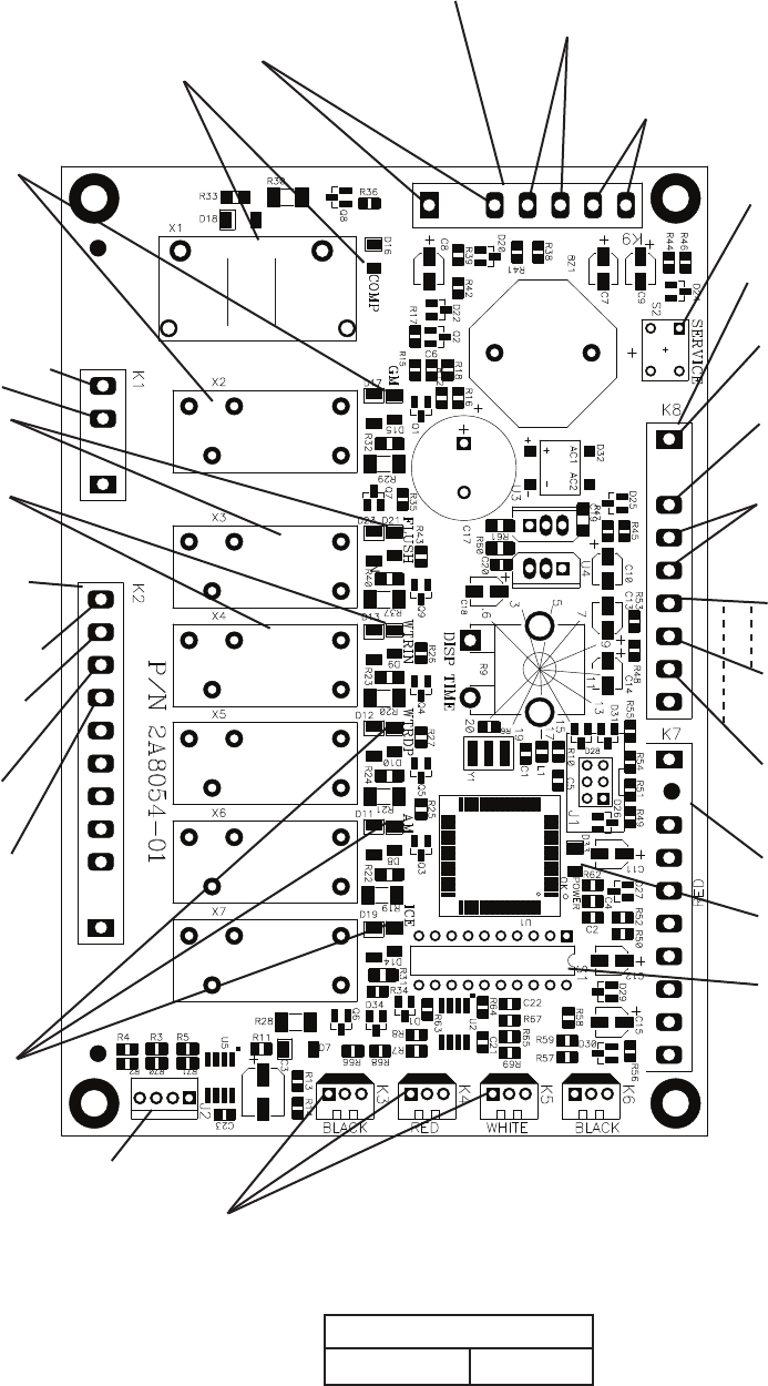
- A. Control Board
- B. Controls and Adjustments
- 1. Default Dip Switch Settings
- 2. Infrared Sensor Shutdown Delay (S1 dip switch 1, 2, 3).
- 3. Drain Frequency Control (S1 dip switch 4)
- 4. Continuous Dispensing Timer (S1 dip switch 5 & 6)
- 5. Bin Control Selector (S1 dip switch 7)
- 6. Agitation and Ice Purge Timer (S1 dip switch 8)
- 7. Mechanical Shutdown Delay (S1 dip switch 9)
- 8. Factory Use (S1 Dip Switch 10)
- C. Power Switch and Control Switch
- IV. Refrigeration Circuit and Component Service Information
- A. Refrigeration Circuit Service Information
- B. Component Service Information
- V. Maintenance
- VI. Disposal
- VII. Technical Information
- A. Specification & Performance Data Sheets
- 1. F-300BAJ
- 2. F-500BAJ
- B. Wiring Diagrams
- 1. F-300BAJ
- 2. F-500BAJ
22
• K1 Connector
(115VAC)
GM, CCR,
EH (-C model), FM, #3
115VAC Input #2
Drain Valve #10
(W/BU)
Control Transformer
24VAC Input
#1 (white/red)
Upper Float Switch
#6 (red) (5VDC)
Compressor Control Relay Circuit/Gear
Motor Protect Relay Circuit
#5 to #6 (white/orange) (5VDC)
High-Pressure Switch
#3 to #4 (yellow) (5VDC)
Control Switch
#1 to #2 (white/black) (5VDC)
• "POWER OK" LED
Control Transformer
24VAC Neutral
#2 (light blue)
Lower Float Switch
#7 (blue) (5VDC)
Float Switch
#5 (black) (5VDC)
• S1 Dip Switch
• K8 Connector
(24VAC and 5VDC)
• K7 Connector-Open
• K2 Connector
(24VAC)
5VDC common terminals
• K3 Connector-Open
• K4 Connector-Open
• K5 Connector-Open
Inlet Water
Valve #8 (O)
3 2 1
(DRAIN)
• J2 Connector-Open
Water Dispensing
Valve, Agitation
Motor, and Ice
Dispensing LEDs
(not used on
these models)
Control Transformer
24VAC Input
#7 (white/red)
Control Transfor mer
24VAC Input
#9 (white/red)
• S2 "SERVICE" Button
(Ice Purge Cycle Bypass)
Bin Control
#3 & #4 (gray) (5VDC)
• "FLUSH" LED
(X3 Relay) (drain)
DV
• "WTRIN" LED
(X4 Relay)
WV
• "GM" LED
(X2 Relay)
GM
• "COMP" LED
(X1 Relay)
Comp
• K9 Connector (5VDC)
Control Board
Part Number
2A8054-01
"F-C" Control Board