
Service Manual


Table Of Contents
- Important Safety Information
- I. Construction and Water/Refrigeration Circuit Diagram
- A. Construction
- B. Icemaking Unit
- C. Water/Refrigeration Circuit Diagram
- II. Sequence of Operation and Service Diagnosis
- A. Sequence of Operation Flow Chart
- 1. Icemaking and Drain Cycle
- 2. Shutdown
- B. Service Diagnosis
- 1. Ice Production Check
- 2. Diagnostic Procedure
- C. Control Board Check
- D. Bin Control Check
- E. Float Switch Check and Cleaning
- F. Diagnostic Tables
- III. Controls and Adjustments
- A. Control Board
- B. Controls and Adjustments
- 1. Default Dip Switch Settings
- 2. Infrared Sensor Shutdown Delay (S1 dip switch 1, 2, 3).
- 3. Drain Frequency Control (S1 dip switch 4)
- 4. Continuous Dispensing Timer (S1 dip switch 5 & 6)
- 5. Bin Control Selector (S1 dip switch 7)
- 6. Agitation and Ice Purge Timer (S1 dip switch 8)
- 7. Mechanical Shutdown Delay (S1 dip switch 9)
- 8. Factory Use (S1 Dip Switch 10)
- C. Power Switch and Control Switch
- IV. Refrigeration Circuit and Component Service Information
- A. Refrigeration Circuit Service Information
- B. Component Service Information
- V. Maintenance
- VI. Disposal
- VII. Technical Information
- A. Specification & Performance Data Sheets
- 1. F-300BAJ
- 2. F-500BAJ
- B. Wiring Diagrams
- 1. F-300BAJ
- 2. F-500BAJ
12
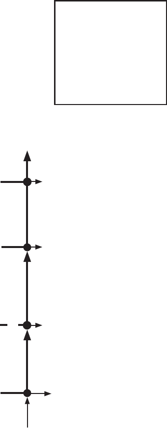
Control Board Sequence of Operation Flow Chart - Shutdown and Re-Start
2. Shutdown
Legend:
BC-bin control
Comp-compressor
DC-drain cycle
DT-drain timer
DV-drain valve
FM-fan motor
FT-ll timer (low water safety)
GM-gear motor
LFS-lower oat switch
PT-purge timer
UFS-upper oat switch
WV-inlet water valve
to "2. Ice Purge Cycle" above if UFS closed.
to "1. Fill Cycle" above if UFS open.
1. Bin Full
GM energized
Comp de-energized
FM de-energized
GM de-energized
3. Icemaker Off
BC open
Comp energized
FM energized
GM energized
2. Ice Purge Cycle
4. Icemaker
Restart
150-sec. Shutdown Sequence
BC closed
4. Bin Control
Shutdown & Restart
BC open
(BC actuator
paddle engaged)
90 sec. 60 sec.