
Instruction Manual
33
5) Use an electronic leak detector or soap bubbles to check for leaks. Add a trace of
refrigerant to the line set copper tubes (if using an electronic leak detector), and then
raise the pressure using nitrogen gas (140 PSIG). WARNING! DO NOT use R-404A as
a mixture with pressurized air for leak testing.
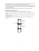
6) Evacuate the line set copper tubes through the charging ports on the Parker quick
connect couplings and charge with R-404A refrigerant vapor to a pressure of 15 to
30 PSIG.
7) Connect the refrigerant lines to the appropriate ttings on the rack system rst (if not
already brazed on), then at the icemaker.
If the couplings to the rack system are not Parker quick connect couplings, follow the
coupling manufacturer's instructions. Make a proper Parker quick connect coupling
connection as follows:
a. Remove the protective covers from the male tting and female coupling.
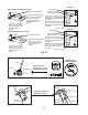
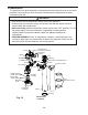
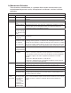
b. Apply Polyol Ester (POE) refrigerant oil to the entire male tting, including threads,
O-ring, and diaphragm, before making the connection. See Fig. 16. NOTICE!
Do not use thread sealant on the ttings. Use POE refrigerant oil or Parker
SuperOLube only.
c. Make sure the male tting and female coupling are properly aligned, then start the
connection by hand to ensure that it is not cross threaded.
d. Place a backup wrench on the back of the female coupling, then tighten the
connection with a wrench until it is tight. At this point, the nut has covered most of
the threads on the male tting. NOTICE! Failure to use a backup wrench may
result in damage to the line set and possible refrigerant leaks.
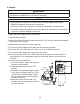
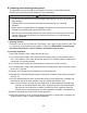
e. Mark a reference line on the female coupling and the unit panel. Using a backup
wrench on the back of the female coupling, tighten the six-sided nut of the female
coupling an additional 1/6 turn. See Fig. 17.
8) Open the rack system service valves.