Hoshizaki Hoshizaki America, Inc. Modular Flaker Models F-450MAH(-C) F-801MAH(-C), MWH(-C) F-1001MAH(-C), MWH(-C), MRH(-C), MLH(-C) F-1500MAH(-C), MWH(-C), MRH(-C) F-2000MWH(-C), MRH(3)(-C), MLH(-C) “A Superior Degree of Reliability” INSTRUCTION MANUAL www.hoshizaki.
WARNING Only qualified service technicians should install and service the appliance. To obtain the name and phone number of your local Hoshizaki Certified Service Representative, visit www.hoshizaki.com. No installation or service should be undertaken until the technician has thoroughly read this Instruction Manual. Likewise, the owner/manager should not proceed to operate the appliance until the installer has instructed them on its proper operation.
IMPORTANT This manual should be read carefully before the appliance is installed and operated. Read the warnings and guidelines contained in this manual carefully as they provide essential information for the continued safe use and maintenance of the appliance. Retain this manual for any further reference that may be necessary. CONTENTS Important Safety Information.................................................................................................. 5 I. Specifications..........................
III. Maintenance.................................................................................................................... 38 A. Maintenance Schedule................................................................................................. 39 B. Cleaning and Sanitizing Instructions............................................................................ 40 IV. Preparing the Icemaker for Periods of Non-Use.............................................................. 44 V. Disposal.......
Important Safety Information Throughout this manual, notices appear to bring your attention to situations which could result in death, serious injury, damage to the appliance, or damage to property. WARNING Indicates a hazardous situation which could result in death or serious injury. NOTICE Indicates a situation which could result in damage to the appliance or property. IMPORTANT Indicates important information about the installation, use, and care of the appliance.
WARNING, continued • The appliance is not intended for use by persons (including children) with reduced physical, sensory, or mental capabilities, or lack of experience and knowledge, unless they have been given supervision or instruction concerning use of the appliance by a person responsible for their safety. • Children should be properly supervised around the appliance. • Do not climb, stand, or hang on the appliance or allow children or animals to do so.
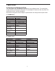
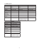
I. Specifications A. Electrical and Refrigerant Data The rating label and nameplate provide electrical and refrigerant data. The rating label can be seen by removing the front panel. The nameplate is located on the rear panel. For certification marks, see the nameplate. We reserve the right to make changes in specifications and design without prior notice. 1. F-450MAH(-C) Single Phase Model Number F-450MAH(-C) AC Supply Voltage 115-120/60/1 Compressor 120V 7.5RLA 54.5LRA Gear Motor 115V 2.
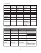
3. F-1001M_H(-C) Model Number AC Supply Voltage F-1001MAH(-C) 208-230/60/1(3 wire with neutral) Compressor 208-230V 5.9RLA 46LRA Gear Motor 120V 3.0FLA 1/4HP Fan Motor 115V 0.85FLA 1/15HP Other 120V 0.03A Maximum Fuse Size 15 AMPS Max. HACR Breaker 15 AMPS (USA Only) Max. Circuit Breaker 15 AMPS (Canada Only) Minimum Circuit 15 AMPS Ampacity Design Pressure HI - 427PSI LO - 230PSI Refrigerant 404A 2 LB. 4.1 OZ. Single Phase F-1001MWH(-C) 208-230/60/1 (3 wire with neutral) 208-230V 5.9RLA 46LRA 120V 3.
5. F-2000M_H(3)(-C) Model Number AC Supply Voltage F-2000MWH(-C) 208-230/60/1 (3 wire with neutral) Compressor 240V 10.8RLA 96LRA Gear Motor 120V 5.6FLA 0.54HP Fan Motor 120V 0.51FLA 8W Other 120V 0.03A (-C is 0.53A) Maximum Fuse Size 30 AMPS Max. HACR Breaker 30 AMPS (USA Only) Max. Circuit Breaker 30 AMPS (Canada Only) Minimum Circuit 30 AMPS Ampacity Design Pressure HI - 460PSI LO - 290PSI Refrigerant 404A 2 LB. 6 OZ. Single Phase F-2000MRH(-C) 208-230/60/1 (3 wire with neutral) 240V 10.
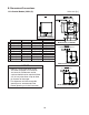
B. Dimensions/Connections Units: mm [in.] 1.
2. Water-Cooled Models (MWH(-C)) Units: mm [in.
3. Remote Models (MRH(3)(-C)) Units: mm [in.
4. Low Side, Parallel Rack System Models (MLH(-C)) Units: mm [in.
5. Remote Condenser Unit URC-5F (use with F-1001MRH(-C)) Units: mm [in.] NOTICE Allow 24" (61 cm) clearance at front and rear for proper air circulation and ease of maintenance and/or service should they be required. Top Rear Icemaker Model F-1001MRH F-1001MRH-C URC-5F Heat of Rejection AT 90°F (32°C) WT 70°F (21°C) 7,660 BTU/hr 7,840 BTU/hr 6. Remote Condenser Unit URC-14F (use with F-1500MRH(-C)) Units: mm [in.
7. Remote Condenser Unit URC-22F (use with F-2000MRH(3)(-C)) Units: mm [in.] NOTICE Allow 24" (61 cm) clearance at front and rear for proper air circulation and ease of maintenance and/or service should they be required.
II. Installation and Operating Instructions WARNING • The appliance must be installed in accordance with applicable national, state, and local codes and regulations. • Failure to install, operate, and maintain the appliance in accordance with this manual will adversely affect safety, performance, component life, and warranty coverage and may result in costly water damage. • CHOKING HAZARD: Ensure all components, fasteners, and thumbscrews are securely in place after installation.
• Remove the protective plastic film from the panels. If the appliance is exposed to the sun or to heat, remove the film after the appliance cools. • Check that the refrigerant lines do not rub or touch lines or other surfaces, and that the fan blade (if applicable) turns freely. • Check that the compressor is snug on all mounting pads. • Flaker models can be installed on an ice storage bin only. Cubelet models can be installed on either a dispenser unit or an ice storage bin.
D. Dispenser Unit/Ice Storage Bin and Icemaker Setup WARNING The installer must ensure the dispenser unit/ice storage bin is compatible with the icemaker, and the dispenser unit/ice storage bin and icemaker are properly attached and secured. 1a) Dispenser Unit: Follow the dispenser unit's setup procedure. Note that only cubelet models can be installed on a dispenser unit; flaker models cannot be installed on a dispenser unit.
E. Electrical Connection WARNING For All Models • Electrical connection must be hard-wired and must meet national, state, and local electrical code requirements. Failure to meet these code requirements could result in death, electric shock, serious injury, fire, or damage. • The icemaker requires an independent power supply of proper capacity. See the nameplate for electrical specifications.
F-450MAH(-C) F-801M_H(-C) F-1001MLH(-C) F-2000MLH(-C) F-1001MAH(-C) F-1001MWH(-C) F-1001MRH(-C) F-1500M_H(-C) F-2000MWH(-C) F-2000MRH(-C) WARNING F-2000MRH3(-C) WARNING ELECTRICAL CONNECTION ELECTRICAL CONNECTION THIS UNIT MUST BE GROUNDED Failure to properly ground or wire this unit could result in death, serious injury, or severe damage to the icemaker. The white lead must be connected to the neutral conductor of the power source. See diagram below.
F. Water Supply and Drain Connections See Fig. 4, 5, and 6 WARNING Water supply and drain connections must be installed in accordance with applicable national, state, and local regulations. NOTICE • Normal operating water temperature must be within 45°F to 90°F (7°C to 32°C). Operation of the appliance, for extended periods, outside of this normal temperature range may affect appliance performance. • Water supply pressure must be a minimum of 10 PSIG and a maximum of 113 PSIG.
1. Icemaker Icemaker Water Supply Inlet 1/2" Female Pipe Thread (FPT) Minimum Icemaker Water Supply Line Size 1/4" Nominal ID Copper Water Tubing or Equivalent Icemaker Drain Outlet 3/4" Female Pipe Thread (FPT) Minimum Icemaker Drain Line Size 3/4" Nominal ID Hard Pipe or Equivalent • An icemaker water supply line shut-off valve and drain valve must be installed. • Be sure there is sufficient extra water supply line and drain line for the appliance to be pulled out for service.
2. Water-Cooled Condenser a) Connection to an Open Drain System Condenser Water Supply Inlet 1/2" Female Pipe Thread (FPT) Minimum Condenser Water Supply Line Size 1/4" Nominal ID Copper Water Tubing or Equivalent Condenser Drain Outlet 3/8" Female Pipe Thread (FPT) Minimum Condenser Drain Line Size 1/4" Nominal ID Hard Pipe or Equivalent • A condenser water supply line shut-off valve and drain valve must be installed. • In some areas, a back flow preventer may be required in the cooling water circuit.
b) Connection to a Closed Loop System Condenser Water Supply Inlet 1/2" Female Pipe Thread (FPT) Minimum Condenser Water Supply Line Size 1/4" Nominal ID Copper Water Tubing or Equivalent Condenser Return Outlet 3/8" Female Pipe Thread (FPT) Minimum Condenser Return Line Size 1/4" Nominal ID Copper Water Tubing or Equivalent • Shut-off valves and drain valves must be installed at both the condenser water supply inlet and condenser return outlet. • Minimum water flow to the condenser is 4 GPM.
G. Installation of Remote Condenser Unit WARNING • Installation of remote condenser unit must be performed by properly trained and EPA-certified service personnel. • The remote condenser unit must be installed in accordance with applicable national, state, and local codes and regulations. • Failure to install the remote condenser unit within these guidelines may adversely affect safety, performance, component life, and warranty coverage.
2. Checks Before Installation 1) Remove the shipping carton, tape, and packing material. 2) Check that the refrigerant lines do not rub or touch lines or other surfaces, and that the fan blades move freely. 3. Setup 1) Secure the legs to the remote condenser unit with the 8 bolts and nuts provided. See Fig. 9. Fig. 9 2) The legs have 8 mounting holes. Secure the legs to the permanent site with 8 bolts (not included). Bolts with Split Lock Washer and Flat Washer Nuts 4.
5. Line Set Installation Precharged factory line sets, available as optional equipment from Hoshizaki America, are recommended. For details, see "II.G.5.a) Factory Line Set Installation." Field fabricated line sets are allowed. For details, see "II.G.5.b) Field Fabricated Line Set Installation." a) Factory Line Set Installation 1) Route the factory line set (see "II.G.4 Line Set Size and Refrigerant Charge" for details) from the remote condenser unit to the icemaker.
3) Evacuate through the Schrader access ports on the Parker quick connect couplings and charge with R-404A refrigerant vapor to a pressure of 15 to 30 PSIG. Go to step 2 in "II.G.5.a) Factory Line Set Installation." b) Field Fabricated Line Set Installation 1) Route the copper tube liquid line and copper tube discharge line (see "II.G.4 Line Set Size and Refrigerant Charge" for details) from the remote condenser unit to the icemaker.
Remote Condenser Unit Icemaker Male Fitting Female Coupling Fig. 10 Discharge Line (Insulated) See "II.G.4 Line Set Size and Refrigerant Charge" for details. Liquid Line (Insulated) See "II.G.4 Line Set Size and Refrigerant Charge" for details. Service Loop F-1001MRH(-C) Remote Condenser Unit Icemaker Male Fitting Female Coupling Discharge Line (Insulated) See "II.G.4 Line Set Size and Refrigerant Charge" for details. Liquid Line (Insulated) See "II.G.
6. Electrical Connection WARNING • Electrical connection must meet national, state, and local electrical code requirements. Failure to meet these code requirements could result in death, electric shock, serious injury, fire, or damage. • To reduce the risk of electric shock, make all remote condenser unit connections before connecting the icemaker power supply. • THE REMOTE CONDENSER UNIT MUST BE GROUNDED.
3) Install a ground wire from the icemaker fan motor junction box to the remote condenser unit junction box. Use wire of an appropriate gage and outdoor rating. 4) Install line and neutral wires from the fan motor leads in the icemaker fan motor junction box to the leads in the remote condenser unit junction box. Use wire of an appropriate gage and outdoor rating. 5) Replace the junction box covers and the louver panel in their correct positions. 7.
H. Connection to an R-404A Parallel Rack System WARNING • Installation must be performed by properly trained and EPA-certified service personnel. • Failure to install the appliance within these guidelines may adversely affect safety, performance, component life, and warranty coverage. NOTICE The icemaker, line set, and rack system must contain the same type of refrigerant. Mixing of refrigerants will result in improper operation and possible damage to the refrigeration system. 1.
5) Use an electronic leak detector or soap bubbles to check for leaks. Add a trace of refrigerant to the line set copper tubes (if using an electronic leak detector), and then raise the pressure using nitrogen gas (140 PSIG). WARNING! DO NOT use R-404A as a mixture with pressurized air for leak testing. 6) Evacuate the line set copper tubes through the charging ports on the Parker quick connect couplings and charge with R-404A refrigerant vapor to a pressure of 15 to 30 PSIG.
Rack System-Threaded Connection Male Threaded Fitting Male Fitting Female Coupling (Charging Ports) Female Threaded Coupling Liquid Line (Insulated) See "II.H.1 Line Set Size and Rack System Requirements" for details. Suction Line (Insulated) See "II.H.1 Line Set Size and Rack System Requirements" for details. Liquid Line (Insulated) See "II.H.1 Line Set Size and Rack System Requirements" F-1001MLH(-C) for details. Service Loop Icemaker Male Fitting Suction Line (Insulated) See "II.H.
I. Final Checklist WARNING CHOKING HAZARD: Ensure all components, fasteners, and thumbscrews are securely in place after installation. Make sure that none have fallen into the dispenser unit/ice storage bin.
J. Startup WARNING All parts are factory-adjusted. Improper adjustments may adversely affect safety, performance, component life, and warranty coverage. NOTICE • If the appliance is turned off, wait for at least 3 minutes before restarting the appliance to prevent damage to the compressor. • At startup, confirm that all internal and external connections are free of leaks. • On remote models, the appliance must have power for a minimum of 4 hours prior to startup to prevent compressor damage.
e) Turn on the power supply to start the automatic icemaking process. WARNING! Keep hands, hair, and loose clothing clear of the cutter on top of the evaporator assembly. Allow the icemaker to run until the compressor starts (approximately 60 seconds). f) Press and hold the actuator paddle located in the top of the chute. The icemaker should shut down within 6 seconds. g) Move the power switch to the "OFF" position, then turn off the power supply.
III. Maintenance The appliance must be maintained in accordance with the instruction manual and labels provided. Consult with your local Hoshizaki Certified Service Representative about maintenance service. WARNING • Only qualified service technicians should service the appliance. • To reduce the risk of electric shock, do not touch the icemaker power switch or control switch with damp hands. • Before Servicing: Move the icemaker's power switch to the "OFF" position. Turn off the power supply.
A. Maintenance Schedule The maintenance schedule below is a guideline. More frequent maintenance may be required depending on water quality, the appliance's environment, and local sanitation regulations. Maintenance Schedule Frequency Area Task Daily Clean the ice scoop using a neutral cleaner. Rinse thoroughly after cleaning. Inspect. Wash with warm water and neutral cleaner if dirty. Check for proper pressure and change if necessary.
B. Cleaning and Sanitizing Instructions The icemaker must be cleaned and sanitized at least twice a year. More frequent cleaning and sanitizing may be required in some conditions. WARNING • To prevent injury to individuals and damage to the icemaker, do not use ammonia type cleaners. • Carefully follow any instructions provided with the cleaning and sanitizing solutions.
10) In bad or severe water conditions, clean the float switch as described below. Otherwise, continue to step 11. a. Remove the float switch from the reservoir cover. b. Wipe down the float switch with the cleaning solution. c. Rinse the float switch thoroughly with clean water. d. Replace the float switch in its correct position. 11) Move the control switch to the "ICE" position, then move the power switch to the "ON" position. Replace the panels in their correct positions.
6) Remove the 2 baffles. 7) Remove the plate and the packing from the top of the ice chute, then remove the bin control assembly by sliding it slightly towards the chute opening and lifting it off. 8) Disassemble the bin control assembly by removing the 2 snap pins, shaft, and actuator.
12) After the gear motor starts, turn off the power supply. Remove the front panel, then move the control switch to the "DRAIN" position. Replace the front panel in its correct position. 13) Turn on the power supply and allow the water system to drain for 5 minutes. 14) Turn off the power supply, then remove the front panel. Move the control switch to the "ICE" position, then replace the front panel in its correct position. 15) Turn on the power supply to start the automatic icemaking process.
IV. Preparing the Icemaker for Periods of Non-Use NOTICE When storing the icemaker for an extended time or in sub-freezing temperatures, follow the instructions below to prevent damage. When the icemaker is not used for two or three days under normal conditions, it is sufficient to only move the power switch to the "OFF" position. When storing the appliance for extended time or in sub-freezing temperatures, follow the instructions below. 1.
3. On water-cooled models, remove the water from the water-cooled condenser: 1) Make sure the power supply is off, then remove the front panel and right side panel. 2) Close the condenser water supply line shut-off valve. If connected to a closed loop system, also close the condenser return line shut-off valve. 3) Open the condenser water supply line drain valve. If connected to a closed loop system, also open the condenser return line drain valve.
V. Disposal The appliance contains refrigerant and must be disposed of in accordance with applicable national, state, and local codes and regulations. Refrigerant must be recovered by properly certified service personnel.
HOSHIZAKI AMERICA, INC. 618 Hwy. 74 S., Peachtree City, GA 30269 USA TEL (770) 487-2331 FAX (770) 487-3360 www.hoshizaki.