Hoshizaki Hoshizaki America, Inc. Self-Contained Cubelet Models C-100BAF C-100BAF-DS C-100BAF-AD C-100BAF-ADDS “A Superior Degree of Reliability” INSTRUCTION MANUAL www.hoshizaki.
IMPORTANT Only qualified service technicians should install, service, and maintain the icemaker. No installation, service, or maintenance should be undertaken until the technician has thoroughly read this Instruction Manual. Likewise, the owner/ manager should not proceed to operate the icemaker until the installer has instructed them on its proper operation.
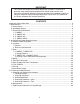
IMPORTANT This manual should be read carefully before the icemaker is installed and operated. Only qualified service technicians should install, service, and maintain the icemaker. Read the warnings contained in this booklet carefully as they give important information regarding safety. Please retain this booklet for any further reference that may be necessary. CONTENTS Important Safety Information.................................................................................................. 4 I.
Important Safety Information Throughout this manual, notices appear to bring your attention to situations which could result in death, serious injury, or damage to the unit. WARNING Indicates a hazardous situation which could result in death or serious injury. CAUTION Indicates a situation which could result in damage to the unit. IMPORTANT Indicates important information about the use and care of the unit.
I. Specifications A.
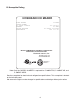
B. Nameplate Rating HOSHIZAKI ICE MAKER MODEL NUMBER SERIAL NUMBER AC SUPPLY VOLTAGE AMPERES DESIGN PRESSURE REFRIGERANT C-100BAF 115-120/60/1 4.0 AMPS HI-240PSI LO-120PSI 134a 3.17 OZ. MOTOR-COMPRESSOR THERMALLY PROTECTED APPROVED FOR OUTDOOR USE Hoshizaki America, Inc. Peachtree City, GA www.hoshizaki.com CONFORMS TO ANSI/NSF 12 ICE MAKER 946Z 3152258 Note: Only the "MODEL NUMBER" is replaced for C-100BAF-DS, C-100BAF-AD, and C-100BAF-ADDS.
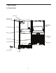
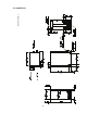
C. Dimensions/Connections Units: mm [in.] 1.
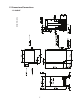
Units: mm [in.] 2.
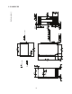
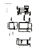
Units: mm [in.] 3.
Units: mm [in.] 4.
II. Installation and Operating Instructions WARNING 1. This icemaker must be installed in accordance with applicable national, state, and local codes and regulations. 2. CHOKING HAZARD: Ensure all components, fasteners, and thumbscrews are securely in place after installation. Make sure that none have fallen into the storage bin. A. Checks Before Installation • Visually inspect the exterior of the shipping container and immediately report any damage to the carrier.
2. Built-In Installation Site CAUTION 1. Do not let the weight of the counter rest on the icemaker. 2. Do not install the icemaker in a corner where the door will interfere with other equipment or where the icemaker cannot be pulled out for service. Installation Space Model Height C-100BAF C-100BAF-DS 34" (864 mm) minimum C-100BAF-AD C-100BAF-ADDS 32" (814 mm) minimum Width Depth 15" (381 mm) minimum 24" (610 mm) minimum Between Two Cabinets C-100BAF C-100BAF-DS Min.
C. Door 1. C-100BAF, C-100BAF-AD a) Hinge Reversal If you would like to reverse the door hinges, follow the steps below. Otherwise, skip to section "II.D. Setup." 1) While maintaining a hold on the door, remove the hinge stop pin from hinge (B). Pull out the bottom of the door slightly and gently remove the door from hinge (A). See Fig. 1. Hinge (B) Hinge (A) Fig. 1 Hinge Stop Pin 2) Remove the 2 screws securing the top panel, then lift it off. See Fig. 2. Top Panel Screws Fig.
4) Remove hinge (B) from the right side of the unit and the 2 filler screws from the left side. Attach the 2 filler screws to the right side and attach hinge (B) to the left side. See Fig. 4. 5) Rotate the top panel 180° from its previous position. This brings the notch that was previously in the right rear to the left front. See Fig. 5. Hook the rear part of the panel on the body, then secure the front with the 2 screws removed in step 2. Top Panel Screws Notch Hinge (B) Filler Screws Fig. 4 Fig.
2. C-100BAF-DS, C-100BAF-ADDS a) Overlay Panel Fabrication and Attachment IMPORTANT The overlay panel must be crafted by a professional cabinet maker to ensure quality results. (1) Parts Ensure that all parts required for the overlay panel assembly are contained in the accessories bag. Overlay Panel Parts No. Description 1 Part Number Qty.
(2) Overlay Panel Specification Use the specification that applies to your icemaker (C-100BAF-DS or C-100BAF-ADDS) and the directions that follow to prepare your overlay panel. ) ) ( ) ( ) ( ) ( ( ) ( ) ) ( ) ( ) ( ( (a) C-100BAF-DS C-100BAF-DS Overlay Panel Specification Overlay Panel Height 29 17/32" (750 mm) Overlay Panel Width 14 13/16" (376 mm) Overlay Panel Thickness 5/8" (16 mm) minimum; 3/4" (19 mm) maximum Overlay Panel and Door Weight (total) 20 lb.
) ) ( ) ( ) ( ) ( ( ) ( ) ) ( ) ( ) ( ( (b) C-100BAF-ADDS C-100BAF-ADDS Overlay Panel Specification Overlay Panel Height 27 9/16" (700 mm) Overlay Panel Width 14 13/16" (376 mm) Overlay Panel Thickness 5/8" (16 mm) minimum; 3/4" (19 mm) maximum Overlay Panel and Door Weight (total) 20 lb.
(3) Fabrication of Overlay Panel Fabricate the overlay panel as outlined in the specification on the previous page and the instructions below. 1) Rout a channel at the bottom of the overlay panel to the proper dimensions. See "(C) Routed Area" in the specification diagram and Fig. 8. 2) Drill six 1/4" diameter (hardwood may require slightly larger diameter) holes 3/8" (10 mm) deep in the locations designated. See "(A) Threaded Inserts" and "(B) Threaded Inserts" in the specification diagram and Fig. 9.
6) If you would like to reverse the door hinges, do the following: a) Contact Hoshizaki Technical Support at 1-800-233-1940 to obtain Hoshizaki Kit HS‑0229. The kit contains "hinge (A)-left." b) Remove the 2 screws securing the top panel, then lift it off. See Fig. 11. c) Remove hinge (A)-right and the bracket from the right side of the unit. Set aside hinge (A)‑right; it is not needed. Remove the top brace from the left side.
7) Remove the bushings from hinge (C1) and hinge (C2) (the hinges attached to the door). See Fig. 16. 8) Remove the gasket from the door. See Fig. 17. Bushing Gasket Hinge Fig. 17 Fig. 16 9) Temporarily fasten the overlay panel to the door using 2 of the M4×25 pan head screws provided. See Fig. 18. CAUTION Ensure that the back surface of overlay panel is flat before attaching. 10) Mark the centerpoint of the hinge (C1) and hinge (C2) holes that extend over the overlay panel. See Fig. 19.
(4) Attachment of Overlay Panel to Door 1) Fasten the sheet metal bracket to the overlay panel using the two M4×8 truss head screws provided. Snug the screws, but do not tighten. See Fig. 20. 2) Temporarily fasten the overlay panel to the door using 2 of the M4×25 pan head screws provided. See Fig. 21. Overlay Panel Screws Snug the screws, but do not tighten. Sheet Metal Bracket Fig. 20 Fig. 21 3) Adjust the sheet metal bracket so that it is flush with the bottom of the door. See Fig. 22.
7) Tighten the four M4×25 pan head screws installed in step 5. See Fig. 26. 8) Replace the door gasket in its proper orientation. Reinsert the bushings into hinge (C1) and hinge (C2) (the hinges attached to the door). See Fig. 27. Bushing Tighten the screws. Gasket Bushing Fig. 26 Fig. 27 9) Attach the door to hinge (A), then continue to maintain a hold on the door. Screw the hinge stop pin into hinge (B) until it is tight. See Fig. 28.
D. Setup 1) Position the icemaker in the selected permanent location. 2) Level the icemaker from side-to-side and front-to-rear by adjusting the feet. E. Electrical Connection WARNING 1. Electrical connection must meet national, state, and local electrical code requirements. Failure to meet these code requirements could result in death, electric shock, serious injury, fire, or severe damage to equipment. 2. This unit requires an independent power supply.
F. Water Supply and Drain Connections WARNING 1. Water supply and drain connections must be installed in accordance with applicable national, state, and local regulations. 2. Normal operating water temperature should be within 45°F to 90°F (7°C to 32°C). Operation of the icemaker, for extended periods, outside of this normal temperature range may affect icemaker performance. 3. To prevent damage to equipment, do not operate the icemaker when the water supply is off, or if the pressure is below 7 PSIG.
G. Final Checklist WARNING CHOKING HAZARD: Ensure all components, fasteners, and thumbscrews are securely in place after installation. Make sure that none have fallen into the storage bin.
H. Startup WARNING 1. All parts are factory-adjusted. Improper adjustments may adversely affect safety, performance, component life, and warranty coverage. 2. If the icemaker is turned off, wait for at least 3 minutes before restarting the icemaker to prevent damage to the compressor. 3. At startup, confirm that all internal and external connections are free of leaks. 1) Open the water supply line shut-off valve. 2) Make sure the power switch is in the "OFF" position.
III. Cleaning and Maintenance This icemaker must be cleaned and maintained in accordance with the instruction manual and labels provided with the icemaker. Consult with your local distributor about cleaning and maintenance service. To obtain the name and phone number of your local distributor, visit www.hoshizaki.com or call Hoshizaki Technical Support at 1‑800‑233‑1940 in the USA. WARNING 1. Only qualified service technicians should attempt to service this icemaker. 2.
3) While maintaining a hold on the door, remove the hinge stop pin from hinge (B). Pull out the bottom of the door slightly, then gently remove the door from hinge (A). See Fig. 31. 4) Remove the 2 screws securing the top panel, then lift it off. 5) Remove all ice from the storage bin. 6) Remove the slope from the storage bin by carefully bending it in the center and releasing it from the 2 slope shafts. 7) Remove the scoop. Remove the 2 thumbscrews securing the scoop holder, then remove it.
12) Allow the icemaker to sit for 10 minutes before operation. If you placed a clamp on the reservoir hose in step 11, remove it before operation and replace the spout in its correct position. 13) Plug the unit back in. Move the power switch to the "ON" position. 14) Allow the unit to make ice using the solution. When ice stops coming out, move the power switch to the "OFF" position. Unplug the unit from the electrical outlet. 15) Remove the drain plug to drain any remaining solution.
5. Sanitizing Procedure - Final 1) Remove the drain plug to drain any remaining solution. 2) After all of the solution has drained, replace the drain plug in its correct position. 3) Remove the reservoir cover. Pour the sanitizing solution into the reservoir until the solution starts to flow through the overflow hose. 4) Allow the icemaker to sit for 10 minutes before operation. 5) Plug the unit back in. Move the power switch to the "ON" position. 6) Allow the unit to make ice using the solution.
B. Maintenance The maintenance schedule below is a guideline. More frequent maintenance may be required depending on water quality, the icemaker's environment, and local sanitation regulations. WARNING 1. Only qualified service technicians should attempt to service this icemaker. 2. Move the power switch to the "OFF" position and unplug the unit from the electrical outlet before servicing. Maintenance Schedule Frequency Area Task Weekly Monthly Clean the scoop using a neutral cleaner.
1. Storage Bin Drain In some conditions, slime may build up inside the storage bin drain and prevent water from draining properly. To prevent this buildup, perform the following procedure once every 3 months or as often as necessary for conditions. 1) Move the power switch to the "OFF" position. 2) Remove all ice from the storage bin. 3) Mix a batch of sanitizing solution by diluting 1.25 fl. oz. (37 ml or 2.5 tbs) of a 5.25% sodium hypochlorite solution (chlorine bleach) with 2.5 gallons (9.
C. Preparing the Icemaker for Long Storage CAUTION When storing the icemaker for an extended time or in sub-freezing temperatures, follow the instructions below to prevent damage. When the icemaker is not used for two or three days under normal conditions, it is sufficient to move the power switch to the "OFF" position. When storing the icemaker for an extended time or in sub-freezing temperatures, follow the instructions below.
HOSHIZAKI AMERICA, INC. 618 Hwy. 74 S., Peachtree City, GA 30269 USA TEL (770) 487-2331 FAX (770) 487-3360 www.hoshizaki.