User Manual for HE-XE100, HE-XE102, HE-XE103, HE-XE104, HE-XE105 HE-XT100, HE-XT102, HE-XT103, HE-XT104, HE-XT105 HEXE220C100/HEXE220C000, HEXT240C100/HEXT240C000 HEXE220C112 / HEXE220C01, HEXT240C112 / HEXT240C012 HEXE220C114 / HEXE220C014, HEXT240C114 / HEXT240C014 HEXE220C113 / HEXE220C013, HEXT240C113 / HEXT240C013 HEXE220C115 / HEXE220C015, HEXT240C115 / HEXT240C015 XLe/XLt OCS MAN0878-04-EN
MAN0878-04-EN PREFACE PREFACE This manual explains how to use the XLe/XLt OCS Modules. Copyright (C) 2008 Horner APG, LLC., 59 South State Avenue, Indianapolis, Indiana 46201. All rights reserved.
Limited Warranty and Liability MAN0878-04-EN LIMITED WARRANTY AND LIMITATION OF LIABILITY Horner APG, LLC. ("HE-APG") warrants to the original purchaser that the XLe/XLt OCS module manufactured by HE-APG is free from defects in material and workmanship under normal use and service.
MAN0878-04-EN Table Of Contents Table of Contents VISUAL MAP OF MAJOR TASKS AND THE KEY CHAPTERS TO ASSIST YOU ................................... 7 CHAPTER 1 : SAFETY / COMPLIANCE .................................................................................................... 9 1.1 Safety Warnings and Guidelines................................................................................................. 9 1.2 Grounding ..............................................................................
Table Of Contents MAN0878-04-EN CHAPTER 7 : COMMUNICATION OPTIONS........................................................................................... 27 7.1 Overview ................................................................................................................................... 27 7.1.1 MJ1 shares ............................................................................................................................ 27 7.2 Ethernet COM Module (XEC) Option.....................
MAN0878-04-EN Table Of Contents 14.2 Cscape Status Bar .................................................................................................................... 71 14.3 Establishing Communications................................................................................................... 72 14.4 Models supported...................................................................................................................... 72 14.5 Configuration.......................................
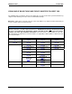
MAN0878-04-EN VISUAL MAP VISUAL MAP OF MAJOR TASKS AND THE KEY CHAPTERS TO ASSIST YOU The following map is provided to show you the major types of tasks needed to be performed and the key chapters in this manual you need to refer to for information and help. Directions: Major tasks are listed at the top of the map with the key chapters listed beneath that you need to consult in order to perform the tasks. FIRST STEP of ANY TASK: DATASHEET Each XLe/XLt unit is sent with a datasheet in the box.
MAN0878-04-EN August 12, 2009 VISUAL MAP Page 8 of 100 ECN # 979
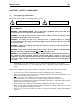
MAN0878-04-EN CH. 1 CHAPTER 1: SAFETY / COMPLIANCE 1.1 Safety Warnings and Guidelines When found on the product, the following symbols specify: Warning: Consult user documentation. Warning: Electrical Shock Hazard. WARNING – EXPLOSION HAZARD – Substitution of components may impair suitability for Class I, Division 2 WARNING – EXPLOSION HAZARD – Do not disconnect equipment unless power has been switched off or the area is known to be non-hazardous.
CH. 1 1.2 MAN0878-04-EN Grounding Grounding is covered in various chapters within this manual. 1.3 For grounding specifications and testing for a good ground, refer to page 21. For panel grounding, refer to 18. CE Compliance To check for compliance and updates, visit our website at: http://www.heapg.com/Pages/TechSupport/ProductCert.
MAN0878-04-EN CH. 2 CHAPTER 2: INTRODUCTION 2.1 Visual Overview of XLe/XLt and Topics Covered in this Manual Removable Media See page 29. User Interface See page 61. General I/O See page 33. High Speed I/O See page 39. Serial Comm See page 23. CAN Comm See page 25. Mechanical Installation See page 15. Electrical Installation See page 21. Figure 2-1 – Visual Overview of XLE/XLT and Topics of Interest Covered in the User Manual 2.1.1 Where to Find Information about the XLe/XLt a.
CH.2 2.2 MAN0878-04-EN Connectivity to the XLe/XLt The XLe/XLt has tremendous capabilities for connecting to a variety of devices. The diagram below shows some examples of devices that can be used with the XLe/XLt.
MAN0878-04-EN 2.4 CH. 2 Required and Suggested Accessories The following list contains a sampling of required and suggested XLe/XLt accessories. Visit our website (see page 96) to view updates on new products and accessories. Note: The XLe/XLt is not shipped with a programming cable in the box. To obtain a programming cable, order HE500CBL300. Table 2.1 – XLe/XLt Accessories Part Number Description HE-XEC 10/100 Ethernet option kit - field installable.
CH.2 2.5 MAN0878-04-EN Useful Documents and References The following information serves as a general listing of Horner controller products and other references of interest with their corresponding manual numbers. Visit our website (see page 96) to obtain user documentation and updates. Note: This list is not intended for users to determine which products are appropriate for their application; controller products differ in the features that they support.
MAN0878-04-EN CH.3 CHAPTER 3: MECHANICAL INSTALLATION Note: Each XLe/XLt unit is sent with a datasheet in the box. The datasheet is the first document you need to refer to for model-specific information related to XLe/XLt models such as pin-outs, jumper settings, and other key installation information. The web version of this manual has all of the XLe/XLt datasheets attached to it. Visit our website (see page 96) to obtain datasheets, user documentation, and updates. 3.
CH. 3 3.2.2 MAN0878-04-EN Mounting Procedures (Installed on DIN Rail) Top Clip Note: Mount the XLe/XLt with the DIN Rail in the horizontal position to avoid slippage. DIN Rail Clip Figure 3-2 – DIN Rail Mounting of the XLe/XLt The XLe/XLt is designed to clip onto standard 35 millimeter DIN rail. If your installation requires liquid or dust protection, make sure the XLe/XLt is placed in an appropriate sealed panel when mounting on DIN rail. Use the following steps to mount the XLe/XLt on DIN rail. 1.
MAN0878-04-EN 3.4 CH.3 Panel Cut-Out 3.622 [92mm] For installations requiring NEMA4X liquid and dust protection the panel cutout should be cut with a tolerance of ± 0.005” (0.1 mm). The XLe/XLt is designed to fit ¼ DIN panel openings. There are a number of punches and enclosures designed to accommodate opening of this size. 3.622 [92mm] 001XLE002 Figure 3-4 – XLe/XLt Panel Cut-out 3.5 Dimensions XLt XLe Note – Your keypad overlay appearance may differ.
CH. 3 3.6 MAN0878-04-EN Factors Affecting Panel Layout Design and Clearances Warning: It is important to follow the requirements of the panel manufacturer and to follow all applicable electrical codes and standards. The designer of a panel layout needs to assess the requirements of a particular system and to consider the following design factors. A convenient checklist is provided on page 19. 3.6.
MAN0878-04-EN 3.6.4 CH.3 Orientation When panel-mounted, there are no orientation restrictions on the XLe/XLt. However, the orientation shown in Figure 3-3 provides for optimum readability of the screen and ease of use of the keypad. When DIN Rail mounted, observe the orientation shown in Figure 3-2. 3.6.5 Noise Consider the impact on the panel layout design and clearance requirements if noise suppression devices are needed.
CH.
MAN0878-04-EN CH. 4 CHAPTER 4: ELECTRICAL INSTALLATION Note: Each XLe/XLt unit is sent with a datasheet in the box. The datasheet is the first document you need to refer to for model-specific information related to XLe/XLt models such as pin-outs, jumper settings, and other key installation information. The web version of this manual has all of the XLe/XLt datasheets attached to it. Visit our website (see page 96) to obtain datasheets, user documentation, and updates. 4.
CH. 4 4.4 MAN0878-04-EN Primary Power Port Table 4.1 – Primary Power Port Pins Pin 1 Signal Description Frame Ground 2 0V Input power supply ground 3 +24V Input power supply positive voltage -+ 10-30 VDC supply - + Power Connector Figure 4-2 – Power Connector (Primary Power Port) -+ Power Up: Connect to Earth Ground. Apply 10 – 30 VDC. Screen lights up. Torque rating 4.5 - 7 Lb-In (0.50 – 0.
MAN0878-04-EN CH. 5 CHAPTER 5: SERIAL COMMUNICATIONS 5.1 Overview All XLe/XLt models provide two serial ports, which are implemented with 8-pin modular RJ45 connectors, and are labeled MJ1 and MJ2. The MJ1 serial port is normally used for XLe/XLt programming by connecting it to the COM port of a PC running Cscape. In addition, both MJ1 and MJ2 can be used for application-specific communication, using a variety of standard data exchange protocols. 5.
CH. 5 5.4 MAN0878-04-EN RS-485 Termination Proper RS-485 termination minimizes reflections and improves reliability. Both serial ports allow an internal 121-Ohm RS-485 termination resistor to be placed across pins 1 and 2. This can be done by installing a jumper. Please refer to the XLe/XLt data sheet for jumper locations. In any case, only the two devices physically located at the endpoints of the RS-485 network should be terminated. 5.
MAN0878-04-EN CH. 6 CHAPTER 6: CAN COMMUNICATIONS Note: For additional CAN information, refer to the CAN Networks manual (MAN0799) on our website. (See page 96 for our website address.) 6.1 Overview Some XLe/XLt models (XE1xx) provide a CAN networking port, which is implemented with a 5-pin connector, labeled NET1. Like the MJ1 serial port, the NET1 port can be used for XLe/XLt programming by connecting it to the CAN port of a PC running Cscape.
CH. 6 6.4 MAN0878-04-EN Cscape Programming via CAN The NET1 port supports CsCAN Programming Protocol. If a PC has a CAN interface installed (via PCI card or USB), and the PC CAN port is connected to the XLe/XLt NET1 port, Cscape can access the XLe/XLt for programming and monitoring. In addition, the XLe/XLt supports single-point-programming of all XLe/XLt and other OCS/RCS devices that are connected to a CAN network.
MAN0878-04-EN CH. 7 CHAPTER 7: COMMUNICATION OPTIONS 7.1 Overview To supplement the built-in MJ1 and MJ2 serial ports (see CHAPTER 5), additional communication options are available. This is accomplished by installing a COM module internal to the XLe/XLt controller. Currently, there are two COM modules available for this purpose: Ethernet (XEC) and Modem (XMC). 7.1.
CH. 7 7.3 MAN0878-04-EN Modem COM Module (XMC) Option A Modem COM module can be installed to allow Cscape programming of an XLe/XLt over a dial-up network. In addition, the application ladder program can take control of the modem for applicationspecific modem communication. The Modem COM module supports the standard AT command set and can connect to the dial-up network at speeds up to 14.4 KBaud. Connection speed is auto-negotiated.
MAN0878-04-EN CH. 8 CHAPTER 8: REMOVABLE MEDIA 8.1 Overview All XLe/XLt models provide a Removable Media slot, labeled Memory, which supports standard Micro SD Flash memory cards. Micro SD cards can be used to save and load applications, to capture graphics screens and to log data for later retrieval. 8.2 Micro SD Cards When the Micro SD card format was introduced, it was originally called TransFlash. Cards labeled either Micro SD or TransFlash, with up to 2.
CH. 8 8.
MAN0878-04-EN 8.7 CH. 8 Using Removable Media to View and Capture Screens The XLe/XLt File System uses bitmap files with the .BMP (.bmp) extension to store XLe/XLt graphic screen captures. To view a captured XLe/XLt screen, use the Removable Media Manager to find and highlight the desired .BMP file, and then press Enter.
CH.
MAN0878-04-EN CH. 9 CHAPTER 9: GENERAL I/O Note: Each XLe/XLt unit is sent with a datasheet in the box. The datasheet is the first document you need to refer to for model-specific information related to XLe/XLt models such as pinouts, jumper settings, and other key installation information. The web version of this manual has all of the XLe/XLt datasheets attached to it. Visit our website (see page 96) to obtain datasheets, user documentation, and updates. 9.
CH. 9 MAN0878-04-EN Once the back is removed the jumper selection can be changed. The jumper settings are documented on each data sheet using a diagram such as Figure 9.2 below and a description of the jumper settings. J4 JP1 J1 J2 JP3 J3 001XLE005-R1 Figure 9-2 – Example Jumper Diagram To re-install the back cover, place the cover back on the unit. The DIN clip should be on the same side as the power connector.
MAN0878-04-EN 9.4 CH. 9 Solid-State Digital Outputs Solid-state digital outputs are generally used to activate lamps, low voltage solenoids, relays and other low voltage and low current devices. Note: The digital outputs used on the XLe/XLt are “sourcing” outputs. This means the output applies a positive voltage to the output pin when turned ON. When turned off, the output applies approximately zero volts with respect to the I/O ground.
CH. 9 MAN0878-04-EN Relay Life – Relays are mechanical devices that have a long but limited life. Typically switching more current limits the life of relays. Please check the data sheets at the end of this manual for expected relay life. Current / Temperature De-Rating – Products containing relays often have total current limits based on the ambient temperature of the application. Please see the product data sheet for current / temperature de-rating information for relays.
MAN0878-04-EN 9.6 CH. 9 Digital Inputs Note: See CHAPTER 10 for high speed I/O information and refer to the datasheet for XLe/XLt model you are using for details on jumper settings. Note: The digital inputs on the XLe/XLt are designed for low voltage DC inputs. The inputs are designed to support both positive and negative input modes. The mode is set by a jumper setting and a configuration parameter in Cscape. All the inputs on the unit must be configured to the same mode. Positive Logic vs.
CH. 9 9.8 MAN0878-04-EN Universal Analog Inputs Note: See the data sheet for the XLe/XLt model you are using for jumper settings and CHAPTER 14 for details on how to use Cscape to configure the digital filtering. The universal analog inputs provide a high resolution, very flexible interface for a variety of analog inputs. These inputs include voltage, current, thermocouple, RTD and millivolt. Each channel can be configured separately using jumpers and configuration settings in Cscape.
MAN0878-04-EN CH. 10 CHAPTER 10: HIGH SPEED I/O (HSC / PWM) 10.1 Overview In addition to the compliment of simple analog and digital I/O, several of the XLe/XLt I/O modules support High Speed Counting (HSC) I/O functions and may also support Pulse Width Modulation (PWM) Output functions. The HSC functions include: frequency, totalizing, pulse width and quadrature measurement.
CH. 10 MAN0878-04-EN Three different options are available to reset the current count. They are: • Configured reset value When configuring the Totalize function, a value may be specified under the Counts per Rev column. When the totalizer accumulator reaches this value - 1, the accumulator will reset to zero on the next count. Specifying zero for this value allows the totalizer to count through the full 32bit range before resetting.
MAN0878-04-EN CH. 10 Width Low 1 µs Counts - In this sub-mode the accumulator value will contain the number of 1 µs counts the pulse is low. Width Low Period Rising Edges 1 µs Counts – In this sub-mode the period of the input signal is reported in one (1) µs units. The period measurement will start on the rising edge of the input. Period from Rising Edge Period Falling Edges 1 µs Counts – In this sub-mode the period of the input signal is reported in one (1) µs units.
CH. 10 MAN0878-04-EN 1 (leading) 2 (lagging) 90° phase Using the above waveforms and a HSC input configuration of “Quadrature” - “1 leads 2, count up,” the accumulator will count up when 1 is rising and 2 is low, 1 is high and 2 is rising, 1 is falling and 2 is high, and when 1 is low and 2 is falling. This results in 4 counts per revolution. So in order to determine the number of cycles, the accumulator would have to be divided by 4.
MAN0878-04-EN CH. 10 Synchronous modes synchronize the reset (or set) to the selected quadrature input and the selected marker polarity. Figure 10.1 below indicates which mode to select based on the markers timing diagram. Consult the documentation provided with your encoder to determine the marker pulse timing. Note that the Marker input is sampled within 50 micro seconds of the associated quadrature edge. It is left to the user to determine if this meets the time constraints of the measured drive.
CH. 10 MAN0878-04-EN The accumulator is reset to zero on the specified edge if rotation is clockwise (as shown in figure 10.1 above). However, if rotation is reversed, the accumulator is alternately set to Counts per rev – 1 on that same physical edge. When direction is reversed, that same physical edge is seen (by the internal decoder) as having the opposite edge polarity as shown below.
MAN0878-04-EN 10.3 HSC Functions Register Map Register %AI5-6 %AI7-8 %AI9-10 %AI11-12 %AQ1-2 %AQ3-4 %Q17 %Q18 %Q19 %Q20 10.4 CH.
CH. 10 MAN0878-04-EN • Period Count This value (%AQ7-8) sets the period of the output signal by specifying the number of internal PWM counter counts before the cycle is reset (larger count results in a smaller frequency). The duration of each count is determined by the prescaler value. This parameter affects the Period of both PWM outputs. See the previous formula to see how the prescale and period counts create an output frequency.
MAN0878-04-EN 10.4.3 CH. 10 HSC (High Speed Counter) When either Q1 or Q2 is configured for HSC operation, HSC1 or HSC2 totalize functions are extended to allow respective direct output control based on a comparison of the current count and a preset value (PV). See totalize in the HSC section above for more information. 10.4.4 Stepper Function When Q1 is configured for Stepper, the stepper function is enabled at the Q1 output. Only one stepper function and output is available.
CH. 10 MAN0878-04-EN The stepper provides two Boolean registers to provide stepper status Ready/Done A high indication on this register (%I30) indicates the stepper sequence can be started (i.e. not currently busy). Error A high indication on this register (%I31) indicates that one of the analog parameters specified above is invalid or the stepper action was aborted before the operation was complete. This register is cleared on the next start command if the error was corrected.
MAN0878-04-EN CH.
CH. 10 MAN0878-04-EN Set %AQ2 = 250 (Hz) {Run Frequency} Set %AQ3-4 = 150000 (Steps) {Accel Count} Set %AQ5-6 = 5500000 (Steps) {Run Count} Set %AQ7-8 = 350000 (Steps) {Decel Count} Note: The highest usable frequency is 65 KHz for the PWM output.
MAN0878-04-EN CH. 11 CHAPTER 11: SYSTEM SETTINGS AND ADJUSTMENTS 11.1 System Menu - Overview The XLe/XLt controller has a built-in System Menu, which lets the user view System Settings and make adjustments. To start the System Menu, press the ↓ and ↑ keys at the same time (or set %SR3 to 1), which will display the Main Menu, as shown in Figure 11-1 and in Figure 11-12. Then use the ↓ and ↑ keys to select a Main Menu item and press Enter to display the item’s Sub-Menu.
CH. 11 MAN0878-04-EN Sub-Menus Sub-Menus Network Ok? Network ID: Network Baud: Yes 253 Port 1: (None Loaded) 125 KB Port 2: (None Loaded) XLt ( Use ↓↑ to adjust ) Fkeys: Momentary Sys-Fn enable: Yes Contrast: (Use ← → to adjust) Model: XTxxxx Mode: Idle Scan Rate(mS): 0.0 Lcl Net Use(%): 0.0 All Net Use(%): 0.0 Ladder Size: 2 Config Size: 8 Graphics Sz: 8 String Size: 8 Bitmap Size: 8 Text Size: 8 Font Size: 8 Protocol Sz: 8 SMS Msg Sz: 8 Firmware Rev: 11.59 CPLD Rev: 1.
MAN0878-04-EN CH. 11 A Sub-Menu generally shows a list of System Settings and their values. After opening a Sub-Menu, if any of its System Settings are editable, the first System Setting that can be edited is highlighted. If desired, the ↓ and ↑ keys can be used to select a different System Setting to be edited. At this point, either press ESC to exit the Sub-Menu (returning to the Main Menu) or press Enter to edit the highlighted System Setting.
CH. 11 MAN0878-04-EN View Status The View Status Sub-Menu displays up to 17 System Settings. The Lcl Net Use % and All Net Use % System Settings only appear for XLe/XLt models that have CAN ports (XE1xx). Only the Mode System Setting is editable.
MAN0878-04-EN CH. 11 The first five System Diagnostics are critical. If any of them indicate a Fault condition, the XLe/XLt will not enter or remain in Run mode, and the problem must be investigated and corrected.
CH. 11 MAN0878-04-EN Internal to the XLe/XLt, there is a CPU board, and up to two installed modules. Models XE000 and XE100 have no installed I/O or COM modules. All other models have an I/O module in Slot 1 and can have a user-installed COM module in Slot 2.
MAN0878-04-EN CH. 11 Set Serial Ports The Set Serial Ports Sub-Menu displays three System Settings, all of which are editable, and one optional item. For the Dflt Pgm Port System Setting, only MJ1-232 can be selected, unless either an Ethernet (XEC) or a Modem (XMC) COM module is installed. Also, the Set Ethernet (Enet) item only appears if an Ethernet COM module is installed.
CH. 11 MAN0878-04-EN Removable Media XLe Specific: The Removable Media Sub-Menu displays the Removable Media Manager (see CHAPTER 8).
MAN0878-04-EN CH. 11 If a directory name is highlighted, pressing Enter will switch to that directory showing its files and subdirectories. In a sub-directory, highlighting .. (dot dot) and pressing Enter will move up one directory Removable Media XLt Specific: The Removable Media Sub-Menu displays the Removable Media Manager (see CHAPTER 8).
CH. 11 MAN0878-04-EN Fail – Safe System The Fail-Safe System is a set of features that allow an application to continue running in the event of certain types of "soft" failures. These "soft" failures include: • Battery power loss • Battery-Backed Register RAM or Application Flash corruption due to, for example, an excessive EMI event.
MAN0878-04-EN Enable AutoRun CH. 11 No Yes = OCS will be in IDLE mode after AutoLoad or Automatic Restore. = OCS will be automatically placed into RUN mode after AutoLoad or Automatic Restore. “Enable AutoLoad” displays the following options which can be selected: XLe: XLt: Enable AutoLoad No Yes = Does not load AUTOLOAD.PGM automatically when application program is absent or corrupted. = Loads AUTOLOAD.PGM file automatically from RM when application program is absent or corrupted.
CH. 11 MAN0878-04-EN Selecting Make Clone brings up the screen below for the user: XLt: XLe: After confirmation, the OCS will create two new files in the root directory of the Removable Media Drive as shown below: AUTOLOAD.PGM CLONE.DAT Application file File having all unit settings and register values from Battery Backed RAM XLe: XLt: Load Clone Selecting “Clone Unit” menu will open the following menu screen. Select “Load Clone”.
MAN0878-04-EN CH. 12 CHAPTER 12: USER INTERFACE 12.1 Screen Navigation The screen navigation on the XLe/XLt is quite flexible. Basic methods will be described here. Control programming can be used to create complex screen navigation techniques. One form of screen navigation is the Jump Screen graphics object. This object is typically tied to a soft key (One of the four keys to the sides of the display for the XLe and at the bottom of the screen for the XLt).
CH.12 12.2 MAN0878-04-EN Ladder Based Screen Navigation Ladder logic can use several techniques to control screen navigation. Coils can be tied to %D registers to make them screen coils. These coils have two modes, switch and alarm. If the ladder program energizes an alarm display coil, the screen associated with this coil is displayed and overrides the normal user screens. This is designed to show alarm conditions or to display other ladder-detected events.
MAN0878-04-EN CH. 12 XLt Specific: The most common editable object is the numeric object. To edit, touch the object and pop-up keypad will appear to allow editing the value. The value chosen by the operator can not exceed the minimum or maximum set by the user program. If the user tries to exceed the maximum point or enter a value below the minimum point, the value does not change.
CH.
MAN0878-04-EN CH. 13 CHAPTER 13: REGISTERS 13.1 Register Definitions When programming the XLe/XLt, data is stored in memory that is segmented into different types. This memory in the controller is referred to as registers. Different groups of registers are defined as either bits or words (16 bits). Multiple registers can usually be used to handle larger storage requirements. For example 16 single bit registers can be used to store a Word or two 16 bit registers can be used to store a 32-bit value.
CH.13 MAN0878-04-EN %S System Bit Single-bit bit coils predefined for system use. %SR System Register 16-bit registers predefined for system use. %T Temporary Bit Non-retentive single-bit registers. 13.2 Useful %S and %SR registers Register %S1 %S2 %S3 %S4 %S5 %S6 %S7 %S8 %S9 %S10 %S11 %S12 %S13 %S16 Register %SR1 %SR2 %SR6 %SR44 %SR45 %SR46 %SR47 %SR48 %SR49 %SR50 %SR56 %SR57 %SR164.3 %SR164.4 %SR164.5 %SR164.6 %SR164.7 %SR164.8 August 12, 2009 Table 13.
MAN0878-04-EN CH. 13 Table 13.2 – Common %SR Register Definitions MAKE_CLONE trigger bit LOAD_CLONE trigger bit Make Clone Fail (This bit goes high when Make / Create Clone fails) Load Clone Fail (This bit goes high when Load Clone fails) Status of the removable media This register shows the amount of free space on the inserted removable media %SR176 to %SR177 in bytes. This is a 32-bit value. This register shows the total size of the inserted removable media in bytes.
CH.13 13.4 MAN0878-04-EN Resource Limits Table 13.3- Resource Limits Resource %S %SR %T %M %R %K %D %I %Q %AI %AQ %IG %QG %AIG %AQG Network Ports Controllers Per Network Keypad Display Screen Memory User Screens Data Fields Per User Screen Ladder Code August 12, 2009 Value 13 192 2048 2048 9999 10 1023 2048 2048 512 512 64 64 32 32 CsCAN (Optional depending on model.
MAN0878-04-EN CH. 14 CHAPTER 14: CSCAPE CONFIGURATION 14.1 Overview XLe/XLt hardware is programmed with a Windows based PC application called Cscape. This application can be used to program, configure, monitor and debug all aspects of the XLe/XLt unit. Please see the on-line help provided with Cscape for additional details. 14.2 Cscape Status Bar When the XLe/XLt is connected to a PC using Cscape software a Status Bar appears at the bottom of the screen.
CH. 14 14.3 MAN0878-04-EN Establishing Communications The main method for communicating between Cscape and an XLe/XLt is RS-232 serial. The XLe/XLt can communicate with Cscape using USB to serial adapters, Ethernet, CAN (CsCAN) or modems. For communications other than RS-232 serial please refer to the manual that ships with the adapter hardware being used for programming. Start by configuring Cscape to use the correct communications port.
MAN0878-04-EN CH. 14 The four areas of I/O configuration are: 14.6 Digital in / HSC Digital out / PWM Analog in Analog out Digital Input / HSC Configuration The following figure illustrates the Digital Input / HSC Configuration dialog. Figure 14-1 – Digital Input / HSC Configuration Dialog The Active mode group box allows the user to select if inputs are active high (Positive logic) or active low (Negative logic). It is important that this setting match what the jumper settings are on the hardware.
CH. 14 MAN0878-04-EN The mode drop-down items are set according to the type selection. The Counts Per Rev. window is enabled/disabled according to the type selection as well. The following table shows what is available with each type selection. Type Disabled Frequency Totalize Pulse Quadrature Marker August 12, 2009 Table 14.1- Count Per Rev Mode Grayed out.
MAN0878-04-EN 14.7 CH. 14 Digital Output / PWM Configuration The following figure illustrates the Digital Output / PWM Configuration dialog. Figure 14-2 – Digital Output / PWM Configuration Dialog The Q1 and Q2 group boxes allow the user to specify the operation of the multi-function outputs. The PWM State On Controller Stop group box contains items that allow the user to specify how the PWM outputs behave when the controller is stopped.
CH. 14 MAN0878-04-EN The Output State On Controller Stop group box contains items to allow the user to specify how the remaining digital outputs behave when the controller is stopped. These items can either hold their value or default to some value when the controller is stopped. 14.8 Analog Input Configuration The following figure illustrates the Analog Input Configuration dialog.
MAN0878-04-EN 14.9 CH. 14 Analog Output Configuration The following figure illustrates the Analog Output Configuration dialog. Figure 14-4 – Analog Output Configuration Dialog The Output value on Stop group box contains items that allow the user to specify how the analog output channels behave when the controller is stopped. The outputs can either hold their value or default to a value when the controller is stopped.
CH.
MAN0878-04-EN CH. 15 CHAPTER 15: FAIL – SAFE SYSTEM 15.1 Overview The Fail-Safe System is a set of features that allow an application to continue running in the event of certain types of "soft" failures. These "soft" failures include: • • Battery power loss Battery-Backed Register RAM or Application Flash corruption due to, for example, an excessive EMI event.
CH. 15 MAN0878-04-EN 4. Set the ‘Enable AutoLoad’ option in the device to YES. 5. Set the ‘Enable AutoRun’ option to YES if the controller needs to be placed in RUN mode automatically after automatic restore of data or AutoLoad operation. 15.3 Backup / Restore Data Selecting this option brings up a screen having four operations: • Backup OCS Data. • Restore OCS Data. • Clear Backup Data.
MAN0878-04-EN CH. 15 XLt: Figure 15-3 – Backup Registers Restore OCS Data: When initiated, this will allow the user to manually copy the backed up data from the onboard FLASH to the Battery-Backed RAM. A restore operation will be automatically initiated if a backup has been previously created and on powerup the Battery-Backed RAM registers fail their check. The following process will be followed for restoring data: • The controller will be placed in IDLE mode.
CH. 15 MAN0878-04-EN Clear Backup Data: When initiated, the backup data will be erased from the onboard Flash and no backup will exist. %SR164.4 and %SR164.3 is reset to 0 when backed up data is erased. XLe: XLt: Figure 15-5 – Clear Backup Data Exit: Goes back to the previous screen.
MAN0878-04-EN CH.
CH. 15 15.4 MAN0878-04-EN AutoLoad This system menu option allows the user to specify whether the OCS automatically loads the application AUTOLOAD.PGM located in Removable Media. When the AutoLoad setting is enabled (set to YES), it can either be manually initiated or automatically initiated at power-up. The automatic initiation will happen only in the following two cases: • When there is no application program in the OCS and a valid AUTOLOAD.PGM is available in the removable media of the device.
MAN0878-04-EN CH.
CH. 15 15.5 MAN0878-04-EN AutoRun This system menu option, when enabled (YES), allows the user to automatically place the OCS into RUN mode after the AutoLoad operation or automatic Restore Data operation. When the AutoRun setting is disabled (NO), the OCS remains in the IDLE mode after a Restore Data or AutoLoad operation. %SR164.5 can be set by putting the system into RUN mode automatically, once an AutoLoad has been performed or an Automatic Restore has occurred.
MAN0878-04-EN CH. 16 CHAPTER 16: CLONE UNIT 16.1 Overview ‘Clone Unit’ feature allows the user to “clone” the OCS of the exact same model. This feature “clones” application program and unit settings stored in Battery backed RAM of an OCS into the RM (refer Removable Media Chapter 8 for details on using RM). It can then be used to clone a different OCS (exact same model). This feature can be used for: • • 16.2 Replacing an OCS by another unit of the same model.
CH. 16 MAN0878-04-EN 3. Make/Create Clone option enables user to duplicate / Clone application file, all unit settings and all register values from Battery Backed RAM. Selecting Make Clone brings up the screen below for the user: XLe: XLt: Figure 16-3 – Clone Unit Confirm Screen After confirmation, the OCS will create two new files in the root directory of the Removable Media Drive as shown below: AUTOLOAD.PGM CLONE.
MAN0878-04-EN CH. 16 Figure 16-5 – Cloning Status Make/Create clone can also be triggered by setting %SR164.9 bit to “1” from Ladder program or graphics. Once the operation is completed, this bit is made zero by the firmware. When Make clone operation is triggered by this SR bit, it does not ask the user for confirmation for making clone. The success / failure of the operation is also not notified on screen to the user. In case of failure of “Make Clone” operation, %SR164.
CH. 16 MAN0878-04-EN 3. User needs to confirm Load Clone as shown below: XLt: XLe: Figure 16-8 – Load Clone Confirm Screen 4. After confirmation, all unit settings and register values will be loaded from Removable media to the Battery backed RAM (Regardless of AutoLoad settings) and then OCS resets for the settings to take effect. NOTE: For security enabled files, Load clone asks for password validation before loading the application. Load clone can also be triggered by setting %SR164.
MAN0878-04-EN CH. 17 CHAPTER 17: MAINTENANCE 17.1 Firmware Updates The XLe/XLt products contain field updatable firmware to allow new features to be added to the product at a later time. Firmware updates should only be performed when a new feature or correction is required. Warning: Firmware updates are only performed when the equipment being controlled by the XLe/XLt is in a safe, non-operational state.
CH. 17 MAN0878-04-EN 17.2.2 Battery Replacement Warning: Lithium Batteries may explode or catch fire if mistreated Do not recharge, disassemble, heat above 100 deg.C (212 deg.F) incinerate, or puncture. Warning: Disposal of lithium batteries must be done in accordance with federal, state, and local regulations. Be sure to consult with the appropriate regulatory agencies before disposing batteries. In addition, do not re-charge, disassemble, heat or incinerate lithium batteries.
MAN0878-04-EN CH. 18 CHAPTER 18: TROUBLESHOOTING / TECHNICAL SUPPORT CHAPTER 18 provides commonly requested troubleshooting information and checklists for the following topics. • • • • Connecting to the XLe/XLt controller Local controller and local I/O CsCAN Network Removable media In the event that this information is not what you need, please contact Technical Support at the locations indicated at the end of this chapter. 18.
CH. 18 MAN0878-04-EN 18.1.1 Connecting Troubleshooting Checklist 1. Programming and debugging must use MJ1. 2. Controller must be powered up. 3. Assure that the correct COM port is selected in Cscape. Tools/Options/Communications Port. 4. Assure that a straight through (non null modem) serial cable is being used between PC and controller. 5. Check that a Loaded Protocol or ladder is not actively using MJ1.
MAN0878-04-EN 18.3 CH. 18 CsCAN Network For complete information on setting up a CsCAN network, refer to CAN Networks manual (MAN0799) by visiting our website (page 96) for the address to obtain documentation and updates. Network status, node ID, errors, and baud rate in the controller system menu are all in reference to the CsCAN network. These indications can provide performance feedback on the CsCAN network and can also be used to aid in troubleshooting.
CH. 18 18.4 MAN0878-04-EN Removable Media 18.4.1 Basic Troubleshooting Description Action XLe/XLt does not read media card. The media card should be formatted with the XLe/XLt. XLe/XLt will not download project file. Make sure the project file is saved as a .pgm file and not a .csp file. 18.5 Technical Support Contacts For manual updates and assistance, contact Technical Support at the following locations: North America: Tel: (317) 916-4274 Fax: (317) 639-4279 Web: www.heapg.
MAN0878-04-EN Index INDEX Accessories, 13 Analog Inputs, 37 Analog Outputs, 38 AutoLoad, 84 AutoRun, 86 Back Cover Removal, 33 Backup / Restore, 80 Battery Replacement, 92 Warnings, 92 When to Replace, 91 Battery backed RAM, 62, 65, 87 CAN Comm Cscape Programming, 26 I/O Expansion (Network I/O), 26 Ladder-Controlled, 26 Overview, 25 Ports, 25 Wiring, 25 CE, 10 Clone Unit, 62, 65, 87 CLONE.
Index Save Applications XLe, 30 Save Applications XLt, 30 View / Capture, 31 Removable Media Manager, 30 Removable Media XLe, 60 Removable Media XLt, 61 RS-485 Biasing, 24 RS-485 Termination, 24 Safety Warnings, Guidelines, 9 Serial Comm Cscape Programming, 24 Downloadable Protocols, 24 Ladder-Controlled, 24 Overview, 23 Ports, 23 Wiring, 23 Set Beeper - XLt, 60 Solid-State Digital Outputs, 35 Sub-Menus, 51 System Menu Details, 53 Navigate / Edit, 52 August 12, 2009 MAN0878-04-EN System Menu Overview, 5
MAN0878-04-EN Table of Figures TABLE OF FIGURES Figure 2-1 – Visual Overview of XLE/XLT and Topics of Interest Covered in the User Manual ................ 11 Figure 2-2 – Visual Overview of Types of Devices that can be connected to XLe/XLt .............................. 12 Figure 3-1 – Panel Mounting of the XLe/XLt and Close-up View of Back .................................................. 15 Figure 3-2 – DIN Rail Mounting of the XLe/XLt....................................................................
Table of Figures August 12, 2009 MAN0878-04-EN Page 100 of 100 ECN # 979