
Instruction Manual

MAN0810-10-EN Specifications / Installation
__________________________________________________________________________________________________________________________________________________________________
12/18/2008 Page 4 of 4 ECN # 947
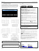
7 Digital Filtering for Analog Inputs
The digital filter is updated once per conversion. It is an “IIR” running average filter
that emulates a simple RC filter. The equivalent time constant is determined by the
Filter Constant and the sum of the conversion times for the two channels. The Filter
Constant determines the weight given to the most recent conversion. The following
table lists the equivalent time constant for the three possible total conversion times,
which are dependent upon the two input mode selections. This filter delay is in
addition to the PLC scan delay.
Equivalent RC Time Constant in Seconds
(Nominal time to reach 63% of final value.)
Total Conversion Time in Seconds
Filter Constant 0.03 0.09 0.13
0* 0.03* 0.09* 0.13*
1 0.07 0.18 0.27
2 0.13 0.35 0.53
3 0.27 0.71 1.07
4 0.53 1.41 2.13
5 1.07 2.83 4.27
6 2.14 5.65 8.54
7 4.28 11.30 17.08
* No filter delay, reading is unfiltered conversion value
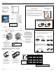
8 Thermocouple Grounding Schemes
Ungrounded Thermocouples
Alternate Shield Connection for
Un
g
rounded Thermocou
p
les.
Ungrounded Thermocouples
Preferred Shield Connection for
Un
g
rounded Thermocou
p
les.
Grounded Thermocouples
Field Ground Potential Less Than
Seven Volts AC
Typical Shield Connection for
Grounded Thermocouples
Grounded Thermocouples
Field Ground Potential Less Than Seven
Volts AC
Shields Connected at One End Only May
be Used to Reduce Noise
Grounded Thermocouples May Use the
Ungrounded Thermocouple Shield
Connections if the Shield is not Grounded
at the Field End
Note: The examples for thermocouple grounding schemes above are generic
illustrations. The XE105 has two thermocouple inputs.
All applicable codes and standards need to be followed in the installation of this
product.
Adhere to the following safety precautions whenever any type of connection is
made to the module:
Connect the safety (earth) ground on the power connector first before making any
other connections.
When connecting to electric circuits or pulse-initiating equipment, open their
related breakers.
Do not
make connections to live power lines.
Make connections to the module first; then connect to the circuit to be monitored.
Route power wires in a safe manner in accordance with good practice and local
codes.
Wear proper personal protective equipment including safety glasses and insulated
gloves when making connections to power circuits.
Ensure hands, shoes, and floor are dry before making any connection to a power
line.
Make sure the unit is turned OFF before making connection to terminals.
Make sure all circuits are de-energized before making connections.
Before each use, inspect all cables for breaks or cracks in the insulation. Replace
immediately if defective.
• Use Copper Conductors in Field Wiring Only, 60/75° C
No part of this publication may be reproduced without the prior agreement and written
permission of Horner APG, Inc. Information in this document is subject to change
without notice.
9 Safety
When found on the product, the following symbols specify:
:Warning: Consult
user documentation.
Warning: Electrical
Shock Hazard.
This equipment is suitable for use in Class I, Division 2, Groups A, B, C and D or
Non-hazardous locations only
WARNING – EXPLOSION HAZARD – Substitution of components may impair
suitability for Class I, Division 2
AVERTISSEMENT - RISQUE D'EXPLOSION - LA SUBSTITUTION DE
COMPOSANTS PEUT RENDRE CE MATERIAL INACCEPTABLE POUR LES
EMPLACEMENTS DE CLASSE 1, DIVISION 2
WARNING – EXPLOSION HAZARD – Do not disconnect equipment unless power
has been switched off or the area is known to be non-hazardous.
AVERTISSEMENT - RISQUE D'EXPLOSION - AVANT DE DECONNECTOR
L'EQUIPMENT, COUPER LE COURANT OU S'ASSURER QUE L'EMPLACEMENT
EST DESIGNE NON DANGEREUX.
WARNING: To avoid the risk of electric shock or burns, always connect the safety
(or earth) ground before making any other connections.
WARNING: To reduce the risk of fire, electrical shock, or physical injury it is strongly
recommended to fuse the voltage measurement inputs. Be sure to locate fuses as
close to the source as possible.
WARNING: Replace fuse with the same type and rating to provide protection against
risk of fire and shock hazards.
WARNING: In the event of repeated failure, do not
replace the fuse again as a
repeated failure indicates a defective condition that will not clear by replacing the
fuse.
WARNING: Only qualified electrical personnel familiar with the construction and
operation of this equipment and the hazards involved should install, adjust, operate,
or service this equipment. Read and understand this manual and other applicable
manuals in their entirety before proceeding. Failure to observe this precaution could
result in severe bodily injury or loss of life.
This device complies with part 15 of the FCC Rules. Operation is subject to the
following two conditions:
1. This device may not cause harmful interference.
2. This device must accept any interference received, including interference that
may cause undesired operation.
10 Technical Support
For assistance and manual updates, contact Technical Support at the following
locations:
North America:
(317) 916-4274
www.heapg.com
email: techsppt@heapg.com
Europe:
(+) 353-21-4321-266
www.horner-apg.com
email:
techsupport@hornerirl.ie