
User Manual

MAN0809-09-EN Specifications / Installation
__________________________________________________________________________________________________________________________________________________________________
12/18/2008 Page 1 of 4 ECN # 947
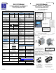
1 Specifications
Specifications
Digital DC Inputs XLE103 XLE104
Digital DC
Outputs
XLE103 XLE104
Inputs per Module
12 including 4
configurable
HSC inputs
24 including
4
configurable
HSC inputs
Outputs per
Module
12 including
2
configurable
PWM
outputs
16 including
2
configurable
PWM
outputs
Commons per
Module
1
Commons per
Module
1
Input Voltage
Range
12 VDC / 24 VDC
Output Type
Sourcing / 10 K Pull-Down
Absolute Max.
Voltage
35 VDC Max.
Absolute Max.
Voltage
28 VDC Max.
Input Impedance
10 kΩ
Output
Protection
Short Circuit
Input Current
Positive
Logic
Negative Logic
Max. Output
Current per
point
0.5 A
Upper Threshold 0.8 mA -1.6 mA
Max. Total
Current
4 A Continuous
Lower Threshold 0.3 mA -2.1 mA
Max. Output
Supply Voltage
30 VDC
Max Upper
Threshold
8 VDC
Minimum Output
Supply Voltage
10 VDC
Min Lower
Threshold
3 VDC
Max. Voltage
Drop at Rated
Current
0.25 VDC
OFF to ON
Response
1 ms
Max. Inrush
Current
650 mA per channel
ON to OFF
Response
1 ms
Min. Load
None
HSC Max.
Switching Rate
10 kHz Totalizer/Pulse,Edges
5 kHz Frequency/Pulse,Width
2.5 kHz Quadrature
OFF to ON
Response
1 ms
Analog Inputs,
Medium
Resolution
XLE103 XLE104
ON to OFF
Response
1 ms
Number of
Channels
2 2
Output
Characteristics
Current Sourcing (Pos logic)
General Specifications
Input Ranges
Safe input voltage
range
Input Impedance
(Clamped @ -0.5
VDC to 12 VDC)
0 - 10 VDC
0 – 20 mA
4 – 20 mA
-0.5 V to +12V
Current Mode:
100 Ω
Voltage Mode:
500 k Ω
Required Power
(Steady State)
130 mA @ 24 VDC
Required Power
(Inrush)
30 A for 1 ms @ 24 VDC
Nominal Resolution
%AI full scale
Max. Over-Current
10 Bits
32,000 counts
35 mA
Primary Power
Range
10 – 30 VDC
Conversion Speed
All channels converted once
per ladder scan
Relative Humidity
5 to 95% Non-
condensing
Max. Error at 25°C
(excluding zero)
4-20 mA 1.00%
0-20 mA 1.00%
0-10 VDC 0.50%
Operating
Temperature
0°C to +50°C
Terminal Type
Screw Type,5 mm
Removable
Additional error for
temperatures other
than 25°C
TBD
CE
UL
See Compliance Table at
http://www.heapg.com/Pages/TechSupport/Prod
uctCert.html
Filtering
160 Hz hash (noise) filter
1-128 scan digital running
average filter
Weight 12.5 oz. (354.36 g)
Clock Accuracy
+/- Seven
Minutes/Month at 20C
Note: Highest usable frequency for PWM output is 65 KHz
XLE OCS Model:
XLE OCS Model:
HE-XE104 / HEXE220C114 / HEXE220C014
HE-XE103 / HEXE220C113 / HEXE220C013
24 Digital DC Inputs / 16 Digital Outputs
12 Digital DC Inputs / 12 Digital Outputs
2 Analog Inputs (Medium Resolution)
2 Analog Inputs (Medium Resolution)
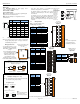
2 Panel Cut-Out and Dimensions
Note: Max. panel thickness: 5 mm.
3.622 [92mm]
3.622 [92mm]
001XLE002
Refer to the XLe/XLt
User Manual for panel
box information and a
handy checklist of
requirements.
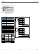
3 Ports / Connectors / Cables
Note: The case of the XLe is black, but for clarity, it is shown in a
lighter gray color.
Note:
The tolerance to meet
NEMA standards is
± 0.005” (0.1 mm).
Note – Your keypad overlay
appearance may differ.
Standard US/EU overlays
pictured here for example.
MJ1
(RS-232 / RS-485)
MJ2
(RS-232 / RS-485)
J1
I/O
Jumper
Memory Slot
001XLE029-R2
J2
I/O
Jumper
NET 1
(CsCAN)
Power
DIP
Switch
To Remove Back Cover:
Unscrew 4 screws located on
the back of the unit and remove
back cover.
CAUTION: Do not over tighten
screws when replacing the back
cover.
001ACC009
Power Connector
Power Up:
Connect to Earth Ground.
Apply 10 – 30 VDC.
Screen lights up.
Torque rating 4.5 - 7 Lb-In
(
0.50
–
0.78 N-m
)
CAN Connector
Use the CAN Connector
when using CsCAN network.
Torque rating 4.5 – 7 Lb-In
(0.50 – 0.78 N-m)
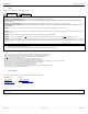
I/O Jumpers (Not Shown): I/O Jumpers (JP) are located
internally. To access, remove back cover of unit.
Wiring Connectors (J1 – J4), I/O Jumpers (JP1-3), and
External Jumpers (RS-485) are described in the Wiring and
Jumpers section of this document.