
User guide
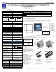

MAN0808-09-EN Specifications / Installation
__________________________________________________________________________________________________________________________________________________________________
12/18/2008 Page 3 of 4 ECN # 947
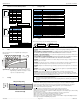
9 I/O Register Map
6 MJ2 Pinouts in Full and Half Duplex Modes
Registers Description
Pin MJ2 Pins
Signal Direction
8
TXD OUT
7
RXD IN
6
0 V Ground
5*
+5 60mA OUT
4
TX- OUT
3
TX+ OUT
2
RX- IN
1
RX+ IN
1
8
%I1 to %I24 Digital Inputs
%I32 Output Fault
%I25 to %I31 Reserved
%Q1 to %Q16 Digital outputs
%Q17 Clear HSC1 accumulator to 0
Totalizer: Clear HSC2
%Q18
Quadrature 1-2: Accumulator 1 Reset to max – 1
%Q19 Clear HSC3 Accumulator to 0
Totalizer: Clear HSC4
%Q20
Quadrature 3-4: Accumulator 3 Reset to max – 1
%Q21 to %Q32 Reserved
%AI1 to %AI4 Analog inputs
* +5 on XLe Rev E and later
%AI5, %AI6 HSC1 Accumulator
%AI7, %AI8 HSC2 Accumulator
MJ2 Full Duplex Mode
%AI9, %AI10 HSC3 Accumulator
%AI11, %AI12 HSC4 Accumulator
MJ2 Half Duplex Mode
Pin MJ2 Pins
Signal Direction
8
TXD OUT
7
RXD IN
6
0 V Ground
5*
+5 60mA OUT
4
TX- OUT
3
TX+ OUT
2
TX-/RX- IN/OUT
1
TX+/RX+ IN/OUT
1
8
* +5 on XLe Rev E and later
%AQ1, %AQ2 PWM1 Duty Cycle
%AQ3, %AQ4 PWM2 Duty Cycle
%AQ5, %AQ6 PWM Prescale
%AQ7, %AQ8 PWM Period
%AQ9 to %AQ14 Analog outputs
Note: Not
all XLe units contain the I/O listed in this table.
10 Safety
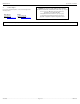
7. Filter
Filter Constant sets the level of digital filtering according to the
following chart.
Digital Filtering. The illustration above demonstrates the effect of
digital filtering (set with Filter Constant) on module
response to a temperature change.
8 Derating
This equipment is suitable for use in Class I, Division 2, Groups A, B, C and D or Non-hazardous locations
only
WARNING – EXPLOSION HAZARD – Substitution of components may impair suitability for Class I,
Division 2
AVERTISSEMENT - RISQUE D'EXPLOSION - LA SUBSTITUTION DE COMPOSANTS PEUT RENDRE
CE MATERIAL INACCEPTABLE POUR LES EMPLACEMENTS DE CLASSE 1, DIVISION 2
WARNING – EXPLOSION HAZARD – Do not disconnect equipment unless power has been switched off or
the area is known to be non-hazardous.
AVERTISSEMENT - RISQUE D'EXPLOSION - AVANT DE DECONNECTOR L'EQUIPMENT, COUPER LE
COURANT OU S'ASSURER QUE L'EMPLACEMENT EST DESIGNE NON DANGEREUX.
WARNING: To avoid the risk of electric shock or burns, always connect the safety (or earth) ground before
making any other connections.
WARNING: To reduce the risk of fire, electrical shock, or physical injury it is strongly recommended to fuse
the voltage measurement inputs. Be sure to locate fuses as close to the source as possible.
WARNING: Replace fuse with the same type and rating to provide protection against risk of fire and shock
hazards.
WARNING: In the event of repeated failure, do
not replace the fuse again as a repeated failure indicates a
defective condition that will
not clear by replacing the fuse.
WARNING: Only qualified electrical personnel familiar with the construction and operation of this
equipment and the hazards involved should install, adjust, operate, or service this equipment. Read and
understand this manual and other applicable manuals in their entirety before proceeding. Failure to observe
this precaution could result in severe bodily injury or loss of life.
When found on the product, the following symbols specify:
Warning: Electrical
Shock Hazard.
Warning: Consult
user documentation.
All applicable codes and standards need to be followed in the installation of this product.
Adhere to the following safety precautions whenever any type of connection is made to the module:
Connect the safety (earth) ground on the power connector first before making any other connections.
When connecting to electric circuits or pulse-initiating equipment, open their related breakers.
Do
not make connections to live power lines.
Make connections to the module first; then connect to the circuit to be monitored.
Route power wires in a safe manner in accordance with good practice and local codes.
Wear proper personal protective equipment including safety glasses and insulated gloves when making
connections to power circuits.
Ensure hands, shoes, and floors are dry before making any connection to a power line.
Make sure the unit is turned OFF before making connection to terminals.
Make sure all circuits are de-energized before making connections.
Before each use, inspect all cables for breaks or cracks in the insulation. Replace immediately if defective.
• Use Copper Conductors in Field Wiring Only, 60/75° C
This device complies with part 15 of the FCC Rules. Operation is subject to the following two conditions:
1. This device may not cause harmful interference.
2. This device must accept any interference received, including interference that may cause undesired
operation.
60
20
10040 8020
0
10
100
90
80
70
60
50
40
30
Scans0
1
Filter
Constant
2 3 4 5 60 7
%Complete [ ]
Relay Life Expectancy
0
10
20
30
40
1234
Contact Current (A)
Operation
(x10
4
)