
Instruction Manual

MAN0886-04-EN Specifications / Installation
__________________________________________________________________________________________________________________________________________________________________
3/2/2010 Page 5 of 6 #1037
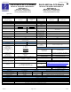
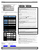
Primary Power Port Pins
Pin Signal Description
1 Ground Frame Ground
2 V- Input Power Supply Ground
3 V+ Input Power Supply Voltage
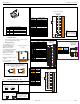
5 Wiring and Jumpers
• Wire according to the type of inputs / outputs used and
select the appropriate jumper option.
•
5.1 I/O Jumpers Settings (JP1 – JP3)
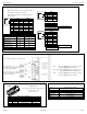
5.2 Wiring Examples
J1
Orange
XL103 / XL104
Name
I1 IN1
I2 IN2
I3 IN3
I4 IN4
I5 IN5
I6 IN6
I7 IN7
I8 IN8
H1 HSC1 / IN9
H2 HSC2 / IN10
H3 HSC3 / IN11
H4 HSC4 / IN12
A1 Analog IN1
A2 Analog IN2
0V Ground
J2 Black
XL103 XL104
0V Ground
V+ V+ *
NC No Connect
OUT13
Q12 OUT12
Q11 OUT11
Q10 OUT10
Q9 OUT9
Q8 OUT8
Q7 OUT7
Q6 OUT6
Q5 OUT5
Q4 OUT4
Q3 OUT3
Q2 OUT2 / PWM2
Q1 OUT1 / PWM1
V+* Supply for Sourcing Outputs
J3
Orange
XT104
I13 IN13
I14 IN14
I15 IN15
I16 IN16
I17 IN17
I18 IN18
I19 IN19
I20 IN20
I21 IN21
I22 IN22
I23 IN23
I24 IN24
0V Ground
Note: The Cscape Module Setup configuration must match the
selected I/O (JP) jumper settings.
I1
0V
001XLE036
12-24VDC
I1
0V
Positive Logic In Negative Logic In
Positive Logic vs. Negative Logic Wiring
The XL6 can be wired for Positive Logic inputs or
Negative Logic inputs.
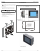
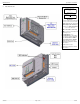
Location of I/O jumpers (JP)
and wiring connectors
(J1 – J4).
Wiring Specifications
For I/O wiring (discrete), use
the following wire type or
equivalent: Belden 9918, 18
AWG (0.8 mm
2
) or larger.
For shielded Analog I/O wiring,
use the following wire type or
equivalent: Belden 8441, 18
AWG (0.8 mm
2
) or larger.
For CAN wiring, use the
following wire type or equivalent:
Belden 3084, 24 AWG (0.2 mm
2
)
or larger.
Use copper conductors in field
wiring only,
60/75° C
Negative Logic
Positive Logic
JP1 Digital DC Inputs
Default
XL104 J3 Orange
Positive Logic
Digital In
J4
Orange
XL104
Q16 OUT16
Q15 OUT15
Q14 OUT14
XL104 J4 Orange
Positive Logic
Digital Out
Q14
Q15
V+
0V
LOAD
LOAD
10 - 30VDC
Q16
LOAD
J2
J4
Note:
When using JP3 (A1-A2),
each channel can be
independently configured.
Note:
Loop Power requirements
are determined by the
transmitter specification.
20mA 10VDC
JP3
CURRENT OR VOLTAGE INPUTS
001XLE043-R1
A1
A2
A1
A2
11
2
2
33
4
4
I1
I2
I3
I4
0V
I5
I6
I7
I8
H1
001XLE046
12-24VDC
LOOP
PWR
20mA
0-10VDC
A1
A2
H2
H3
H4
XL103 / 104 J1 Orange
Positive Logic
Digital In
J1
J2
J3
JP3
JP1
001XLE005-R1
J4
Q1
Q2
Q3
Q4
Q9
Q10
Q11
Q12
Q5
Q6
Q7
Q8
V+
0V
LOAD
LOAD
LOAD
LOAD
LOAD
LOAD
LOAD
LOAD
LOAD
LOAD
LOAD
LOAD
10 - 30VDC
Q13
001XLE024
LOAD
XL103 / 104 J2 Black
Positive Logic
Digital Out
I13
I14
I15
I16
I22
I23
I24
0V
I17
I18
I19
I20
I21
001XLE047
12-24VDC
4.5 Power Port and Wiring