
User Manual

SUP0740-07 CH.2
11/30/2009 Page 11 of 98 # 958
CHAPTER 2: INSTALLATION
2.1 Built-In Ethernet Module
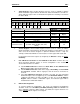
As shown in Table 1.1 (page
7), for some OCS Models, the SmartStack Ethernet Module is built-
in to the OCS unit, requiring no
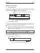
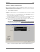
user-installation. For example, Figure 2.1 shows the location of
the RJ-45 Ethernet connector on OCS451, OCS551 and OCS651 units.
Ethernet Connector (OCS551 and OCS651) Ethernet Connector
(OCS451)
Figure 2-1 – SVGA Color Graphics OCS Bottom View
2.2 User-Installed Ethernet Module
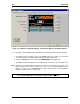
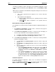
For other OCS or RCS Models, the SmartStack Ethernet Module must be user-installed on the
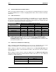
back of the OCS / RCS unit. Figure 2.2 shows the locations of the Ethernet RJ-45 connector and
LED indicators on the user-installed SmartStack Ethernet Module.
Note: Normally, a user-installed Ethernet Module occupies the first I/O slot on the back of the
OCS or RCS unit. The only exception to this rule occurs if a FOX100 Module is also
installed. In this case, the FOX100 Module occupies the first I/O slot, and the Ethernet
Module is installed into the second I/O slot.
For more details on installing SmartStack I/O modules, refer to Chapter 2 of the Control Station
Hardware Manual (MAN0227), which also provides a handy checklist concerning panel box
layout and minimum clearance requirements.
Link & Activity LEDs Ethernet Connector
Figure 2-2– User-Installed Ethernet Module Side View
Caution: For proper functioning and to avoid possible damage, do not install more than
four SmartStack Modules on the back of an OCS or RCS controller.