Supplement for HE800ETN200, HE800ETN300 HE-ETN200, HE-ETN300 SmartStack™ Ethernet Modules SUP0740-07
SUP0740-07 PREFACE PREFACE This manual explains how to use SmartStack Ethernet Modules (ETN200 and ETN300). Copyright (C) 2006 Horner APG, LLC, 59 South State Avenue, Indianapolis, Indiana 46201. All rights reserved.
WARRANTY AND LIABILITY SUP0740-07 LIMITED WARRANTY AND LIMITATION OF LIABILITY Horner APG, LLC ("HE-APG") warrants to the original purchaser that the ETN200 / 300 manufactured by HE-APG is free from defects in material and workmanship under normal use and service.
TABLE OF CONTENT SUP0740-07 TABLE OF CONTENTS PREFACE ......................................................................................................................... 2 LIMITED WARRANTY AND LIMITATION OF LIABILITY ............................................... 3 CHAPTER 1: INTRODUCTION ....................................................................................... 7 1.1 1.2 1.3 1.4 1.5 1.6 Ethernet Modules Overview .......................................................................
SUP0740-07 TABLE OF CONTENT 6.6 EGD Operation............................................................................................................. 40 6.7 EGD Status Words ....................................................................................................... 40 6.7.1 EGD Produced Exchange Status Words ................................................................. 40 6.7.2 EGD Consumed Exchange Status Words ............................................................... 41 6.
TABLE OF CONTENT SUP0740-07 B. Additional E-Mail Configuration ........................................................................... 80 C. Email Message Configuration ............................................................................. 83 C.1. Email Directory .................................................................................................... 83 C.2. Outgoing Messages............................................................................................. 86 12.
SUP0740-07 CH.1 CHAPTER 1: INTRODUCTION 1.1 Ethernet Modules Overview Note: HE800ETN200 and HE800ETN300 have metal cases. HE-ETN200 and HE-ETN300 have plastic cases. The modules are alike except that they have different case materials. In this supplement, Ethernet modules are referred to as ETN200 / 300 regardless of the type of case material used. Ethernet Modules are built-in or user-installed into Horner OCS controllers to provide advanced Ethernet communication capabilities.
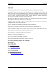
CH.1 SUP0740-07 Protocol / Feature ICMP Ping EGD (Peer) SRTP Server Table 1.
SUP0740-07 CH.1 1.3 Ethernet System Requirements and Interoperability Full Ethernet functionality requires: ¾ ¾ ¾ PC running Cscape Programming Software Version 7.0c or later (for configuration) OCS controller with built-in or user-installed Ethernet Module (ETN200 / ETN300) FTP & HTTP protocols supported only by OCS Models with built-in Ethernet and Compact Flash/Micro SD.
CH.1 1.5 SUP0740-07 Additional Technical Resources It is assumed that the user has a working knowledge of Ethernet networks and Horner OCS / RCS controllers. The following references are available to assist the user in these areas. For a technical summary of Ethernet and other information, refer to: http://www.techfest.com/networking/lan/ethernet.htm For Horner OCS / RCS controller technical support, refer to: http://www.heapg.com/Pages/techsupport.
SUP0740-07 CH.2 CHAPTER 2: INSTALLATION 2.1 Built-In Ethernet Module As shown in Table 1.1 (page 7), for some OCS Models, the SmartStack Ethernet Module is builtin to the OCS unit, requiring no user-installation. For example, Figure 2.1 shows the location of the RJ-45 Ethernet connector on OCS451, OCS551 and OCS651 units. Ethernet Connector (OCS551 and OCS651) Ethernet Connector (OCS451) Figure 2-1 – SVGA Color Graphics OCS Bottom View 2.
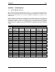
CH.2 2.3 SUP0740-07 Network Administrator Installation Notes When connecting an Ethernet Module to a local network, the following information is provided to the Network Administrator, as an aid in configuring Ethernet Hubs, Routers, Switches, Gateways and Servers. 2.3.1 UDP and TCP Ports Each protocol supported by the Ethernet Module (except ICMP) uses one or more UDP and/or TCP Ports as the destination port for all messaging, as shown in Table 2.1. (Note: Any port can be used as the source port.
SUP0740-07 CH.2 Ethernet Switches normally don’t support Multicast IP Addressing, while Ethernet Hubs do support Multicast IP Addressing. Some Ethernet Routers, known as Multicast Routers, do support Multicast IP Addressing, by using Internet Group Management Protocol (IGMP). Note: For those customers wanting to use Multicast Routers to connect EGD devices, the Ethernet Module automatically handles IGMP communication with Multicast Routers.
CH.2 2.4 SUP0740-07 Safety When found on the product, the following symbols specify: Warning: Consult user documentation. Warning: Electrical Shock Hazard. WARNING: Remove power from the OCS controller, CAN port, and any peripheral equipment connected to this local system before adding or replacing this or any module. WARNING: To avoid the risk of electric shock or burns, always connect the safety (or earth) ground before making any other connections.
SUP0740-07 CH.3 CHAPTER 3: GENERAL CONFIGURATION Note: The following configuration is required for all applications regardless of the protocols used. Additional configuration procedures must be performed for each protocol used as described in the configuration sections of the next several chapters. 3.1 Ethernet Module Configuration To configure the Ethernet Module, use Cscape Programming Software to perform the following six steps: 1.
CH.3 SUP0740-07 Figure 3-2– Hardware Configuration Dialog – OCS Models With User-Installable Ethernet 3. To configure a user-installable Ethernet Module into a SmartStack I/O slot, do the following: a. Referring to Figure 3.2 above, click on the Config button to the right of the desired I/O slot, which will open the Add I/O Module dialog, as shown in Figure 3.3. b. Click the Comm tab and select the desired HE800ETNxxx item from the list. c. Click OK.
SUP0740-07 CH.3 Figure 3.3– Add I/O Module Dialog – Comm Tab and Ethernet Module Selected Figure 3.
CH.3 SUP0740-07 4. Now it is time to configure the Ethernet Module as appropriate for the application. Referring to Figure 3.1 or 3.4 above, click the Config button to the right of the Ethernet Module, and then select the Module Setup tab, revealing the Ethernet Module Configuration dialog (Figure 3.5). Figure 3.5– Ethernet Module Configuration Dialog - Module Setup Tab Selected 5. Configure the Ethernet Module parameters as follows: It has two parts 1. Register Usage and 2.
SUP0740-07 iv. CH.3 Status Register: Enter an OCS Register reference (such as %R100) to indicate which 16-bit OCS register will have the Ethernet Status word written to it. Table 3.1 shows how this register value is formatted and explains the meaning of each bit in the Status Word. Bit 16 Bit 15 Bit 14 Table 3.
CH.3 SUP0740-07 As with the IP Address register (described in the Standard Configuration section below), Net Mask and Gateway register Directions can be set to Read Only or Read / Write With Cscape 8.2 onwards, the ETN Module Configuration dialog has been enhanced to support the following: 1. More easily expanded Protocol Support list for current and future protocols. 2. Optional Enhanced Configuration: a. Allows Net Mask and Gateway to be optionally read from or written to OCS registers. b.
SUP0740-07 CH.3 Note that the assigned IP Address register’s Direction can set to Read only or Read / Write. If the register is Read only, the Default IP Address becomes the unit’s IP Address and is loaded into the assigned register, where it can be read by the application. (Note: In this case, the low octet of the IP Address can be replaced with the unit’s CAN Network ID, by checking the Use CAN ID for last Octet checkbox.
CH.3 3.2.3 9 SUP0740-07 IP Address from OCS Register Use CAN ID for last Octet IP Address Direction (Read / Write) In this mode, the Ethernet Module’s IP Address comes from an OCS register. The IP Address Register parameter indicates which 32-bit OCS registers to read the IP Address from. The static IP Address parameter is not used in this situation, except to set the Default IP Address in nonvolatile memory.
SUP0740-07 CH.4 CHAPTER 4: CSCAN OVER ETHERNET PROTOCOL 4.1 CsCAN over Ethernet Overview This chapter describes CsCAN TCP Server Communication protocol, also known as CsCAN over Ethernet protocol. CsCAN over Ethernet protocol allows a CsCAN Host Programming Tool, such as Cscape, to access an OCS unit, as though it were connected directly to the OCS programming serial port. 4.
CH.4 SUP0740-07 2. Select the Ethernet from the Connection Medium list, and then set the Target IP Address and Timeout parameters as follows: Target IP Address: Enter the IP Address previously assigned to the target Ethernet Module. Please refer to Chapter 3 regarding how to assign an IP Address to an Ethernet Module. Timeout: Enter a number between 1000 and 65,000 (in milliseconds) for the maximum expected network round-trip communication time.
SUP0740-07 CH.4 Figure 4.2 – I/O Configuration Download Warning 4.4.1 How to Prevent Losing Communication Before using CsCAN over Ethernet to download a new I/O Configuration, to an OCS with an Ethernet Module installed, the application programmer should: 1. Make sure the new I/O Configuration contains an Ethernet Module configuration. 2. Make sure the new Ethernet configuration will not change the IP Address.
CH.4 SUP0740-07 4. If this does not succeed, try changing Cscape’s Target IP Address (Figure 4.1) to match the static IP Address parameter (even if it is grayed out). 5. If all else fails, connect a PC running Cscape directly to the target OCS unit’s programming serial port, repeat the download, and then use Data Watch to examine the register indicated by the IP Addr Register parameter (Figure 3.5 [page 18]), to discover the Ethernet Module’s new IP Address.
SUP0740-07 CH.4 6. Click on the Items to Protect Setup button to open the Administrator’s Security Settings dialog, as shown in Figure 4.4. Figure 4.4– Administrator’s Security Settings Dialog 7. To password-protect CsCAN over Ethernet protocol, make sure the CsCAN TCP (Ethernet) checkbox is checked in the Administrator’s Security Settings dialog, as shown in Figure 4.4. Then click OK. 8. The Administrator password is always authorized for all protected features.
CH.
SUP0740-07 CH.5 CHAPTER 5: INTERNET CONTROL MESSAGE PROTOCOL (ICMP) 5.1 ICMP Overview ICMP is used for diagnostic purposes only, to determine if another device exists on the Ethernet network. Using ICMP, the Ethernet Module sends Ping Echo Requests to another device, and expects the other device to answer with Ping Echo Responses. The Ethernet Module measures the round-trip time of each Ping Echo Request / Response exchange and puts the result (in milliseconds) into an OCS register.
CH.5 SUP0740-07 Ping Time Reg: Enter an OCS Register reference (such as %R202) to indicate which 32-bit OCS register will be written with the Ping Echo Request / Response round-trip time (in milliseconds). Ping Timeout: Enter a number between 100 and 100,000 for how often (in milliseconds) the Ethernet Module should send Ping Echo Requests. 5. Click OK to accept the new ICMP Configuration. 5.
SUP0740-07 CH.6 CHAPTER 6: ETHERNET GLOBAL DATA PROTOCOL (EGD) 6.1 EGD Overview Ethernet Global Data (EGD) protocol is a GE Fanuc Automation protocol, which is designed for simple, efficient data exchanges between peer devices on a network. EGD protocol communicates using the UDP transport layer. Although this method of data transfer is very efficient, it has no specific way to detect and recover lost data packets.
CH.6 6.3 SUP0740-07 EGD Configuration If EGD protocol will be used in the application, EGD Configuration must be performed, in addition to the general Ethernet Module Configuration previously described in Chapter 3. To configure EGD protocol, use Cscape Programming Software to perform the following six steps: 1. Open the Ethernet Module Configuration dialog (Figure 3.5 [page 18]) as described in Chapter 3. 2.
SUP0740-07 CH.6 Figure 6.2 – Ethernet Global Data (EGD) Configuration Dialog – Consumed Exchange Tab Selected 4. Follow the steps in Section 6.4 to configure Produced Exchanges, as necessary for the application. 5. Follow the steps in Section 6.5 to configure Consumed Exchanges, as necessary for the application. 6. Click OK to accept the new EGD Configuration. 6.4 EGD Produced Exchange Configuration To configure EGD Produced Exchanges, open the Ethernet Global Data Configuration dialog (Figure 6.
CH.6 SUP0740-07 When defining I/O Blocks for a Produced Exchange, the application programmer selects what type and how much information will be associated with the Exchange. For Produced Exchanges, there are two types of I/O Blocks to choose from: Data and Status. Table 6.2 shows these I/O Block Types along with their definitions: Table 6.
SUP0740-07 CH.6 Exchange Number: Enter a number between 1 and 16,383, which will be used to identify the Exchange to be sent. IP Address Radio Button: Select this option if the Exchange will be sent to a specific Consumer. (This will cause the next edit box to be for entering IP Address, instead of Group ID.) Group ID Radio Button: Select this option if the Exchange will be sent to a Group of Consumers. (This will cause the next edit box to be for entering Group ID, instead of IP Address.
CH.6 SUP0740-07 Figure 6.4– Add I/O Range to Exchange Dialog 2. Configure the I/O Block parameters as follows: Type: Select Data Type to define a block of OCS registers, which the Produced Exchange will periodically read and send to the EGD network. Select Status Type to define a 16-bit OCS register, which will be written with the Produced Exchange’s Status Word.
SUP0740-07 CH.6 When creating a Consumed Exchange, the application programmer selects an Exchange Number for it, determines whether to receive the Exchange as a single Consumer or as a member of a Group of Consumers, chooses which Producer to receive the Exchange from, and sets how often to expect the Exchange to be received. When defining I/O Blocks for a Consumed Exchange, the application programmer selects what type and how much information will be associated with the Exchange.
CH.6 SUP0740-07 1. In the Ethernet Global Data Configuration dialog (Figure 6.2), click on the Add Exch button to open the Add / Edit Consumed Exchange dialog (Figure 6.5). Figure 6.5– Add / Edit Consumed Exchange Dialog 2. Configure the Consumed Exchange parameters as follows: Exchange Number: Enter a number between 1 and 16,383, which will be used to identify the Exchange to be received. Producer IP Address: Enter the IP Address of the Producer to receive the Exchange from.
SUP0740-07 6.5.2 CH.6 Defining EGD Consumed Exchange I/O Blocks After creating a Consumed Exchange (Section 6.5.1), one or more I/O Blocks should be defined for it. An I/O Block specifies what type and how much information will be associated with the Consumed Exchange. To define I/O Blocks for a Consumed Exchange, perform the following six steps: 1. In the upper window of the Ethernet Global Data Configuration dialog (Figure 6.
CH.6 6.6 SUP0740-07 EGD Operation Unlike other protocols, EGD protocol stops completely when the OCS (or RCS) is not in RUN mode. In this case, EGD Produced Exchanges are not transmitted, and all received Consumed Exchanges are ignored. As soon as an OCS (or RCS), containing a configured Ethernet Module, is placed into RUN mode, it will start exchanging EGD messages with other EGD devices on the network, as follows: 1. The Ethernet Module will transmit each configured Produced Exchange (see Section 6.
SUP0740-07 6.7.2 CH.6 EGD Consumed Exchange Status Words The Status Word for an EGD Consumed Exchange can take on the following values: 0 IDLE - No new status event has occurred. The Ethernet Module initializes all Status Words to 0, only at power-up and each time the OCS enters RUN mode. Subsequently, the OCS application ladder program can write the value 0 to the Status Word, as an aid in knowing when Ethernet Global Data consumption occurs (see Status Words 1 and 7). 1 OK - Data Consumed.
CH.6 6.8.1 SUP0740-07 EGD Example 1 – Configuring Node 1 To configure Node 1 for EGD Example 1, as shown in Figure 6.6, perform the following six steps: 1. On the main Cscape screen, select New on the File menu to start a new user program. Then open the Ethernet Module Configuration dialog (Chapter 3, Figure 3.5 [page 18]), and fill in the parameters for Node 1, as shown in Figure 6.7 below. In this example, Node 1 will have a Static IP Address (Section 3.2.
SUP0740-07 CH.6 Figure 6.8– Creating Produced Exchange 1 - Node 1 3. Click on the Add Range button, in the EGD Configuration dialog, to define a Data Block for Produced Exchange 1. Then fill in the parameters, as shown in Figure 6.9 below, and click OK. In this example, Node 1 will use Exchange 1, to transmit 10 words of data taken from %R100 through %R109. Figure 6.
CH.6 SUP0740-07 Figure 6.10– Configured Produced Exchange 1 - Node 1 4. Now that Exchange 1 has been configured as a Produced Exchange for Node 1, it is time to configure Exchange 2 as a Consumed Exchange for Node 1. To do this, first select the Consumed Exchanges tab (Figure 6.2) and click on the Add Exch button to create a Consumed Exchange. Then fill in the parameters, as shown in Figure 6.11 below, and click OK.
SUP0740-07 CH.6 Figure 6.11– Creating Consumed Exchange 2 - Node 1 5. Click on the Add Range button, in the EGD Configuration dialog, to define a Data Block for Consumed Exchange 2. Then fill in the parameters, as shown in Figure 6.12 below, and click OK. In this example, Node 1 will use Exchange 2, to receive 5 data words into %R200 through %R204. Figure 6.
CH.6 SUP0740-07 Figure 6.13 – Configured Consumed Exchange 2 - Node 1 6. Node 1 configuration is now complete. Click OK, save the user program using an appropriate filename, such as EGD Node 1.csp, and then continue with Section 6.8.2 to perform Node 2 configuration.
SUP0740-07 6.8.2 CH.6 EGD Example 1 – Configuring Node 2 To configure Node 2 for EGD Example 1, as shown in Figure 6.6, perform the following six steps: 1. On the main Cscape screen, select New on the File menu to start a new user program. Then open the Ethernet Module Configuration dialog (Chapter 3, Figure 3.5 [page 18]), and fill in the parameters for Node 2, as shown in Figure 6.14 below. In this example, Node 2 will have a Static IP Address (Section 3.3.
CH.6 SUP0740-07 Figure 6.15 – Creating Produced Exchange 2 - Node 2 3. Click on the Add Range button, in the EGD Configuration dialog, to define a Data Block for Produced Exchange 2. Then fill in the parameters, as shown in Figure 6.16 below, and click OK. In this example, Node 2 will use Exchange 2, to transmit 5 words of data taken from %R100 through %R104. Figure 6.
SUP0740-07 CH.6 Figure 6.17 – Configured Produced Exchange 2 - Node 2 4. Now that Exchange 2 has been configured as a Produced Exchange for Node 2, it is time to configure Exchange 1 as a Consumed Exchange for Node 2. To do this, first select the Consumed Exchanges tab (Figure 6.2 [page 33]) and click on the Add Exch button to create a Consumed Exchange. Then fill in the parameters, as shown in Figure 6.18 below, and click OK.
CH.6 SUP0740-07 Figure 6.18 - Creating Consumed Exchange 1 - Node 2 5. Click on the Add Range button, in the EGD Configuration dialog, to define a Data Block for Consumed Exchange 1. Then fill in the parameters, as shown in Figure 6.19 below, and click OK. In this example, Node 2 will use Exchange 1, to receive 10 data words into %R200 through %R209. Figure 6.
SUP0740-07 CH.6 Figure 6.20 – Configured Consumed Exchange 1 - Node 2 6. Node 2 configuration is now complete. Click OK, save the user program using an appropriate filename, such as EGD Node 2.csp, and then continue with Section 6.8.3, to start EGD communication between Node 1 and Node 2. 6.8.3 EGD Example 1 – Starting EGD Communication between Node 1 and Node 2 Now that both Node 1 and Node 2 have been configured for EGD Example 1 (Figure 6.6), start them communicating as follows: 1.
CH.6 6.9 SUP0740-07 EGD Example 2 Building upon EGD Example 1, EGD Example 2 will demonstrate how to add Status, Timestamp, and Filler Blocks to Exchanges in Node 1. 6.9.1 EGD Example 2 – Adding a Status Block To get a Produced or Consumed Exchange’s Status Word (Section 6.7 [page 40]) into an OCS register, define a Status Block for the Exchange. To do this for Node 1’s Produced Exchange 1, for example, perform the following two steps: 1.
SUP0740-07 CH.6 Figure 6.22 – Produced Exchange 1 with Status Block – Node 1 6.9.2 EGD Example 2 – Adding an OCS Timestamp Block In EGD protocol, a timestamp is sent with every Produced Exchange, indicating when the Producer sampled the data being sent. For a Consumer of the Exchange to get this information into an OCS register, define an OCS Timestamp Block for the Consumed Exchange. To do this for Node 1’s Consumed Exchange 2, for example, perform the following 2 steps: 1.
CH.6 SUP0740-07 Figure 6.23 – Consumed Exchange 2 OCS Timestamp Block Definition – Node 1 In this example, when Node 1 receives Consumed Exchange 2 from Node 2, its timestamp will be converted into a 14-byte OCS-format timestamp, and will be written into the Node 1 registers %R220 through %R226. Notice that the Number of Bytes parameter is not configurable and will always be 14 for an OCS Timestamp Block.
SUP0740-07 6.9.3 CH.6 EGD Example 2 – Adding a Filler Block Sometimes a Consumer does not need all of the data sent by a Producer in an Exchange. In this case, the Consumed Exchange’s Data Block should be defined to receive fewer registers than will be sent by the Producer of the Exchange. However, if the partial data needed by the Consumer is not at the beginning of the data received in an Exchange, there must be some way to skip (ignore) the extra data.
CH.6 SUP0740-07 . Figure 6.
SUP0740-07 CH.7 CHAPTER 7: SERVICE REQUEST TRANSFER PROTOCOL (SRTP) 7.1 SRTP Overview Service Request Transfer Protocol (SRTP) is a GE Fanuc Automation protocol, which allows a remote SRTP Client to request services from an SRTP Server. In this context, the Ethernet Module acts as an SRTP Server, which responds to requests from one or more SRTP Clients.
CH.7 SUP0740-07 2. Enable SRTP by checking the SRTP Slave (90-30 Service Request) checkbox in the Module Configuration dialog (Figure 3.5). No additional configuration is required for SRTP protocol. As long as SRTP is enabled and the Ethernet Module has been assigned an IP Address and Net Mask, it will respond to service requests from an SRTP Client, such as a PC running GE Fanuc CIMPLICITY Plant Edition software. 7.
SUP0740-07 CH.8 CHAPTER 8: MODBUS TCP SLAVE PROTOCOL 8.1 Modbus Overview Modbus TCP is a Master / Slave protocol, which allows a remote Modbus TCP Master (client) to request services from a Modbus TCP Slave (server). In this context, the Ethernet Module acts as a Modbus TCP Slave, which responds to requests from one or more Modbus TCP Masters. All Modbus requests that contain the Ethernet Module’s IP Address are serviced.
CH.8 8.2 SUP0740-07 Modbus Configuration If Modbus TCP Slave protocol will be used in the application, the general Ethernet Module Configuration, previously described in Chapter 3, must be performed, and Modbus must be enabled. To enable Modbus protocol, use Cscape Programming Software, to perform the following two steps: 1. Open the Ethernet Module Configuration dialog (Figure 3.5 [page 18]), as described in Chapter 3. 2.
SUP0740-07 CH.8 3. A Modbus TCP Master can determine if the OCS is RUN mode in either of the following two ways: a. By reading the OCS Always On register (%S7), which is 1 if the OCS is in RUN mode and 0 if the OCS is not in RUN mode (because of item 2 above). b. By issuing a Read Exception Status request, which returns an Exception Status of 0 if the OCS is in RUN Mode or 1 if the OCS is not in RUN mode. 4. When “Write Inhibit” is enabled in the configuration: a.
CH.
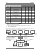
SUP0740-07 CH.9 CHAPTER 9: ETHERNET/IP PROTOCOL 9.1 Ethernet/IP Overview Ethernet/IP protocol is ODVA’s Common Industrial Protocol (CIP) over Ethernet. Figure 9.1 illustrates the protocol layers. Ethernet/IP starts at the Ethernet Physical Layer, and moves up through the IP, TCP/UDP, and Encapsulation Layers. It is beyond the scope of this supplement to discuss the specifics of the Ethernet/IP protocol. See the Ethernet/IP specification at http://www.odva.
CH.9 SUP0740-07 The Ethernet Module supports Class 3 connections for explicit messaging, and Class 1 connections for I/O (Implicit) messaging. The Ethernet Module can be configured to produce and consume 0 bytes of data up to 256 bytes of data. The TCP connections used for Ethernet/IP have an inactivity timeout of 60 seconds. In the event of an inactivity timeout, the TCP connection will automatically close. 9.
SUP0740-07 9.3 CH.9 Ethernet/IP Operation After configuring the Ethernet Module as described in section 9.2, it is ready to respond to Ethernet/IP requests. The Ethernet Module handles unconnected requests anytime. In order to exchange I/O data with the Ethernet Module, a class 1 connection pair must be established. The connection pair consists of a class 1 originator-to-target connection and a class 1 target-to-originator connection, both of which should be set for point-to-point Transport Type.
CH.
SUP0740-07 CH.10 CHAPTER 10: FTP SERVER PROTOCOL 10.1 FTP Overview File Transfer Protocol (FTP) is a standard Client/Server Internet protocol, based on RFC959, which supports efficient and reliable file transfers over a TCP/IP network. In this context, the Ethernet Module acts as an FTP Server, which responds to file transfer requests from one or more FTP Clients. Note: As indicated in Table 1.
CH.10 SUP0740-07 4. Optionally, set up the FTP Configuration parameters for User 1 and/or User 2 as follows: User Name: Name. Password: Password. Read Only: system. Read / Write: system.
SUP0740-07 CH.10 Also, the OCS file system allows multiple concurrent file accessing. For example, an FTP Client can read a file at the same time the OCS ladder program is logging data to another file. It is also possible for both the FTP Client and OCS ladder functions to read the same file at the same time.
CH.
SUP0740-07 CH.11 CHAPTER 11: HTTP SERVER PROTOCOL 11.1 HTTP Overview HyperText Transfer Protocol (HTTP) is a standard Client/Server Internet protocol, based on RFC1945, which transfers web content over a TCP/IP network. In this context, the Ethernet Module acts as an HTTP Server (web content provider), which responds to requests from HTTP Clients (web browsers). Note: As indicated in Table 1.
CH.11 SUP0740-07 4. Optionally, set up the HTTP Configuration parameters for User 1 as follows: User Name: Name. Password: Password. Read Only: Read / Write: Note: Enter an alphanumeric string (up to 40 characters) for the HTTP Client’s User Enter an alphanumeric string (up to 40 characters) for the HTTP Client’s This option is always deselected and grayed out. This option is always selected and grayed out.
SUP0740-07 CH.11 consist of up to 8 characters, followed by an optional dot, and an optional extension with up to 3 characters. Web content files can be stored into the OCS file system media (such as Compact Flash / Micro SD), by temporarily plugging the media into a PC with an installed card reader, or via Ethernet using FTP (File Transfer Protocol). See Chapter 10 for information on using the Ethernet Module FTP Server.
CH.11 ¾ SUP0740-07 For BOOL formatting (see next section), a bit number can be appended to 16-bit register references (%R, %AI and %AQ). For example, reg–R11.3 references bit 3 of register %R11. Valid bit numbers are 1 through 16. 11.5.2.2 FMT PARAMETER – OCS REGISTER READ FORMAT Examples: fmt–BOOL fmt–BOOL–ON–OFF fmt–BOOL–YES–NO fmt–BIN fmt–HEX fmt–INT fmt–UINT fmt–DINT fmt–UDINT fmt–REAL fmt–REAL–E fmt–ASCII–10 fmt–IPADR The required fmt parameter is followed by a dash and a display format type.
SUP0740-07 Note: CH.11 When using an Internet Explorer browser to view OCS web pages that employ the rfs parameter, the browser plays the currently configured Start Navigation sound (a short “tick” by default) for each refresh. To disable the “ticking”, (1) open the Windows Control Panel, (2) click the Sounds or Sound and Audio Devices icon or link and (3) turn off the Start Navigation sound by selecting (None) for it in the drop-down list. 11.5.2.
CH.11 SUP0740-07
In the following example, the first tag creates an ON button that can be clicked to turn %T22 On, while the second tag creates an OFF button that can be clicked to turn %T22 Off. CH.11 SUP0740-07 HTML Editors are specially enhanced text editors designed specifically to make web page creation easier, but they still require a great deal of HTML knowledge. WYSIWYG (What You See Is What You Get) Programs allow HTML code creation using drag and drop techniques, and thus promise to minimize the author’s need to understand HTML. However, when problems arise, there is no substitute for getting into the generated HTML code to see what is going on.
SUP0740-07 CH.12 CHAPTER 12: Email (SMTP Protocol) 12.1 Overview Electronic mail, often abbreviated as email or e-mail, is a method of exchanging digital messages, designed primarily for human use. Email has been implemented using SMTP (Simple Mail Transfer Protocol) protocol in OCS. An electronic mail message consists of two components, the message header, and the message body, which is the email's content.
CH.12 SUP0740-07 Figure 12.1 – E-Mail Configuration Dialog Select Enable Email Configuration to begin email configuration. A. E-Mail Status Register Configuration Address Name Status Register Settings Enter the starting register location to indicate the status of the Email communication. Enter (or select) an I/O Name. B. Additional E-Mail Configuration Click on E-Mail Server Configuration to configure Email address, Server Address and authentication. The following dialog would be opened.
SUP0740-07 CH.12 Figure 12.2 – E-Mail Server Configuration Dialog If the user wants to provide the email configuration through registers, ‘Get Settings from Register’ checkbox can be enabled. In this case the entire configuration data is taken from registers as shown below.
CH.12 SUP0740-07 Figure 12.3 – E-Mail Server Configuration Dialog Email Server Settings E-Mail Address 11/30/2009 The Email address of the controller can be configured here. If the user wants to provide email address through register, the Get Settings from Register checkbox can be clicked and register reference can be provided in E-mail Address edit-box. The register mentioned here should contain the email address followed by null termination or space.
SUP0740-07 CH.12 SMTP Server IP: The SMTP Server IP address of the email service provider needs to be provided here. In case SMTP server IP needs to be obtained from DNS server, select Obtain SMTP Server IP Address from DNS Server checkbox. This will enable DNS Server IP and SMTP Server Name edit-boxes. Configure these with the information provided by email service provider. SMTP Server Port: The default port for email configuration is set to 25 but can be changed by user if required.
CH.12 SUP0740-07 Figure 12.4 – E-Mail Target Directory • Click Add Contact to add a contact. Following screen Email Directory will appear. • Click Modify Contact if a contact is already added in the directory. (You will see information about the contacts in the above screen.) To modify the contact, either doubleclick the row or highlight the row and click Modify Contact. The Modify Contact Information screen appears, where the contact can be modified.
SUP0740-07 CH.12 New Contact Information Group Name Enter or select a Group Name. 1. It can contain characters A-Z, a-z, 0-9, and the _ underscore character. 2. The first character must be A-Z, a-z, or the _ underscore character. 3. Do not use spaces or special characters. Email ID 4. Do not use two consecutive underscore characters. Either enter an Email ID or enter a register where the email ID is stored.
CH.12 SUP0740-07 C.2. Outgoing Messages Note: Before creating send Emails, a directory needs to be created. Upto to 128 different emails can be configured. Figure 12.7 – E-Mail Send Mails • Click Add New Message to add a new Email message format.(i.e. Email body) • Click Modify Message to edit a message that is already in the list. Either double-click the row or highlight the row and click Modify Message. • Click Delete Message to remove a message after highlighting the row.
SUP0740-07 CH.12 Figure 12.8 – Message/E-Mail Configuration Trigger Variable Settings Email Message Configuration An event is needed to trigger an Email communication from the controller to the member(s) of a Group. Enter a bit reference in the Address field that (when set to HIGH) causes the Email message associated with the trigger to be sent to the specified Group member(s). An I/O name can be entered or selected in the Name field.
CH.12 SUP0740-07 Message/EMail Configuration Messages can contain text and register data values, which approved group members can read from the controller's data registers at runtime. • Enter the subject of the email communication. • Enter the body of email. • In order to edit/add register data values, click F2 = Insert Field button and configure the Insert Value Field screen shown below: Figure 12.
SUP0740-07 CH.12 Figure 12.10 – Select a Character to Insert • Click OK to return to the Email Configuration screen. 12.3 Email Status Email Status Register is 32bit long entity and details are as follows: Bit No 1 2 Error Invalid Configuration Error Invalid IP or Port address 3 Socket Error 4 Bind Error 5 Connection Timeout Error 6 Transmit Buffer Error. Transmit Error. 7 8 9 UDP Resource Error DNS Error Response.
CH.12 SUP0740-07 10 DNS Response Timeout No response received from DNS server. Check configured DNS server IP address. 11 SMTP Command Timeout No response received from Email server for Email command sent. 12 SMTP Error Response Error response received from Email Server for Email command sent. Check configured Email server name (or IP address), Port address, Email address (To and From), Username and Password.
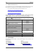
SUP0740-07 CH.13 CHAPTER 13: ASCII over TCP/IP 13.1 Overview This protocol is designed to send and receive ASCII data over Ethernet port of the controllers. Controller acts as a server while using this protocol. Minimum version requirements for ASCII over TCP/IP feature: - Firmware 12.6 - Cscape 9 13.2 Configuration a. Open CSCAPE and click on menu option. Select a controller with Ethernet port. b. Click on Config button for Ethernet. Click Here Figure 13.
CH.13 c. SUP0740-07 Select module setup in the Module Configuration window. Figure 13.2 – Module Configuration d. In module configuration window set up IP address, Net mask, Gateway, and select ASCII over TCP/IP checkbox and the click on Configure Selected Protocol as shown below: Click Here Figure 13.
SUP0740-07 CH.13 e. In ASCII over TCP/IP Configuration window configure Port Number, register for start address of Transmit data, register for start address for Receive data, Transmission Trigger Register and Status Address. Port Number can be provided directly or by using register address. For port number entry using register user has to select option. Figure 13.4 – ASCII over TCP/IP Configuration 13.
CH.13 SUP0740-07 13.4 Receiving ASCII characters from the client In above configuration dialog %R500 register is used for receiving data. The receive data register format will be as below. Sl.No 1 Register Address %R500 2 %R501 3 4 %R502 %R503 .. .. %R(500+n-1) n Data Content First Register contains number of byes (characters) received. User can provide valid termination character here (if any). If there is no termination character set this register value to zero. Received data.
SUP0740-07 INDEX INDEX A ASCII, 94 B Built-In Ethernet Module, 11 C Configuration CsCAN Protocol, 23 EGD Protocol, 32 Ethernet Module, 15 Ethernet/IP Protocol, 64 FTP Protocol, 67 HTTP Protocol, 71 ICMP Protocol, 29 Modbus Protocol, 60 SRTP Protcol, 57 CsCAN Protocol Configuration, 23 Downloading Precautions, 24 Operation, 24 Overview, 23 Preventing Loss of Communication, 25 Recovering from Lost Communication, 25 Security, 26 F FTP Protocol Configuration, 67 File Accessing, 68 Operation, 68 Overview, 67
INDEX Overview, 29 Internet Connectivity, 13 IP Address, 18, 21 SUP0740-06 HTTP Protocol, 71, 79 ICMP Protocol, 29 Modbus Protocol, 59 SRTP Protocol, 57 M Modbus Protocol Configuration, 60 Master Mapping, 59 Operation, 60 Overview, 59 N Net Mask, 18 O Operation CsCAN Protocol, 24 EGD Protocol, 40 Ethernet/IP Protocol, 65 FTP Protocol, 68 HTTP Protocol, 72 ICMP Protocol, 30 Modbus Protocol, 60 SRTP Protocol, 58 Overview CsCAN Protocol, 23 EGD Protocol, 31 Ethernet Module, 7 Ethernet/IP Protocol, 63 FTP P
SUP0740-07 TABLE OF FIGURES TABLE OF FIGURES Figure 1.1– Example of an Ethernet Network ................................................................................. 8 Figure 2-1 – SVGA Color Graphics OCS Bottom View ................................................................. 11 Figure 2-2– User-Installed Ethernet Module Side View ................................................................ 11 Figure 3-1 – Hardware Configuration Dialog – OCS Models With Built-In Ethernet ....................
TABLE OF FIGURES SUP0740-06 Figure 12.9 – Insert Value Field .................................................................................................... 88 Figure 12.10 – Select a Character to Insert .................................................................................. 89 Figure 13.1 – Hardware Configuration .......................................................................................... 91 Figure 13.2 – Module Configuration .................................................