
User guide


PAGE 4 26 JUL 2004 MAN0416-04
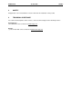
2.2.3 RS-232 Programming Port and Wiring
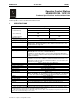
Table 4– RS-232 Port Pins
Pin Signal Description Direction
1 DCD Always high Out
2 RXD Received Data Out
3 TXD Transmitted Data In
4 DTR Data Terminal Ready In
5 GND Ground -
6 DSR Data Set Ready Out
7 RTS Request to Send In
8 CTS Clear to Send Out
9 RI Ring Indicate Out
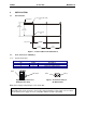
Figure 7 – RS-232 Port
The OCS units feature an RS-232 port (Programming/Debug) for connection to a personal computer.
This port is used for the purposes of OCS programming, configuring, monitoring, and debugging. This
port can also be used for general ladder logic controlled serial communications to printers, modems,
terminals, etc. When ladder has control of this port, it is not available for programming or debugging. The
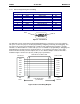
wiring diagram for the RS-232 port is shown in Figure 8. If a permanent connection is to be made
between the OCS and the personal computer, the use of a shielded, multiple conductor wire with a
maximum length of 15.24 meters (50 feet) enables proper performance.
Figure 8- OCS to PC Wiring Diagram
Pin 9
Pin 1
OCS RS-232 9-PIN PC COM
SHIELDED MULTI CONDUCTOR
DCD 1
1 DCD
RXD 2
TXD 3
DTR 4
GND 5
DSR 6
RTS 7
CTS 8
RI 9
2 RXD
3 TXD
4 DTR
5 GND
6 DSR
7 RTS
8 CTS
9 RI
DB9
MALE
DB9
FEMALE
15.24 METERS MAX
(50 FEET MAX)