
Instruction Manual

PAGE 4 15 JAN 2010 MAN0432-04
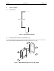
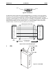
Figure 5 – Network Connector Figure 6 – As viewed at the RCS
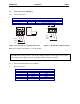
b. Grounding
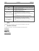
Figure 7 – Grounding Method
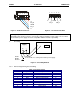
2.3.3 RS-232 Programming Port and Wiring
Table 4– RS-232 Port Pins
Pin Signal Description Direction
1 DCD Always high Out
2 RXD Received Data Out
3 TXD Transmitted Data In
4 DTR Data Terminal Ready In
5 GND Ground -
6 DSR Data Set Ready Out
7 RTS Request to Send In
8 CTS Clear to Send Out
9 RI Ring Indicate Out
V+
CN_H
SHLD
CN_L
V
-
1 2 3 4 5
V-
CN_L
SHLD
CN_H
V+
1 2 3 4 5
Warning:
To provide maximum noise immunity and to ensure minimum EMI radiation, the V-
signal (DC power return) need to be connected to earth ground at the power supply. The user must
ensure that the power supply selected is compatible with this method of grounding.
DC Power
Supply
+ -
RCS
+
-
Frame
(Earth)
Ground
Connect DC V- to earth ground at the power supply.