
Instruction Manual


Table Of Contents
MAN0970-04-EN RCC972 Specifications / Installation
10 Diagnostics
LED - Normal Functionality
LED
Off
ON
Flash (1Hz)
PWR
No power
applied
10-30Vdc
applied
OK
Self test fail
Self test pass
I/O forcing
enabled.
RUN
Stop mode
Run Mode
Do I/O Mode.
Switch - Normal Functionality
Load switch
1. Pressing the LOAD switch during power-up boots from the Micro SD card. This starts a Firmware Load if the Micro SD is bootable
and valid firmware files are found on it.
2. After boot-up, pressing the LOAD switch for 3 seconds either starts a Firmware Load or an Application Load depending upon what
files are found on the Micro SD. If firmware files are found, a Firmware Load is performed. If firmware files are not found and the
DEFAULT.PGM file is found, an Application Load is performed.
Run/Stop switch
1. After boot-up, pressing the RUN/STOP switch for 3 seconds toggles the RCC between RUN and STOP modes.
Switch – Erase Program Function
LOAD and RUN/STOP
1. After boot-up, pressing both Load and RUN/Stop switches for 3 seconds performs an “Erase All” function, which deletes all
application programs.
LED – Diagnostic Functionality
The leds are also used to indicate some fault conditions in the unit. The two leds OK and RUN will flash a number of times depending upon
the fault. There will be a two second gap and the pattern will be repeated. The number of flashes and the associated error are as follows:
No. of flashes
Fault Meaning
2
The MAC ID is empty.
3
The internal MAC file is corrupt.
4
The MAC ID TXT file is invalid.
5
The MAC ID file is not found or the uSD card is empty or missing system files.
Diagnostic Led flashing table.
LED Load Program/Firmware Functionality
LED
OK & RUN
Flashing
Alternately
Flashing
Together
Flashing Stops
Load program
or firmwre
Download in Progress
Download fails,
number of flashes
indicates the error.
Download Complete,
unit reboots (allow 30
seconds).
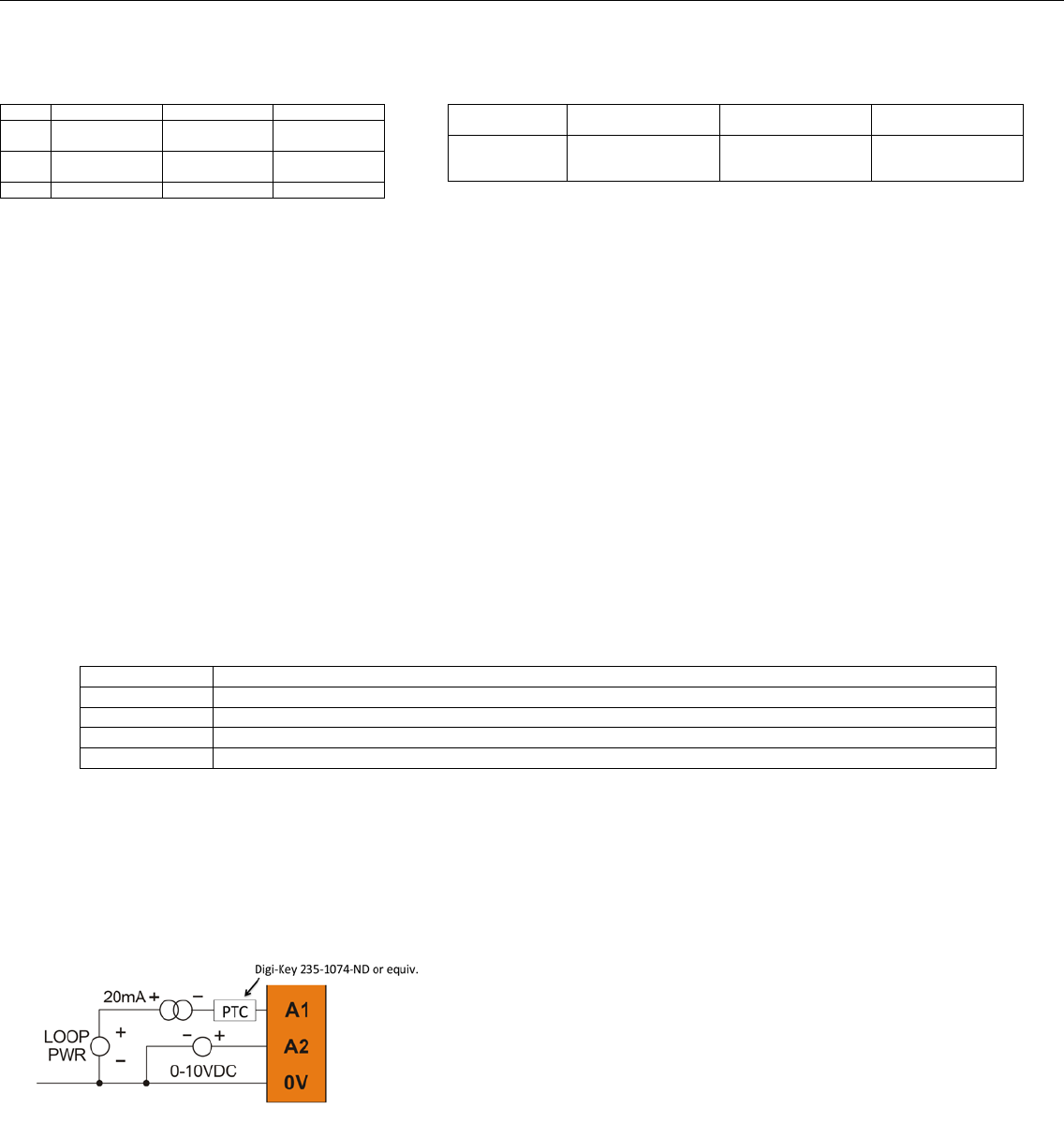
11. Common Cause of Analog Input Tranzorb Failure
A common cause of Analog Input Tranzorb Failure on Analog Inputs Model 2, 3, 4 & 5: If a 4-20mA circuit is initially wired with loop
power, but without a load, the Analog input could see 24Vdc. This is higher than the rating of the tranzorb. This can be solved by NOT
connecting loop power prior to load connection, or by installing a low-cost PTC in series between the load and Analog input. See
SUP0977-01 for additional details.
__________________________________________________________________________________________________________________________________________________________________
6/20/2013 Page 4 of 4 ECN
No part of this publication may be reproduced without the prior agreement and written permission of Horner APG, Inc. Information in this document is subject to change without notice.