OWNER'S MANUAL LOCK-N-LOAD ® AP RELOADING PRESS ™
ASSEMBLY Table of Contents ASSEMBLY AP Press.......................................................................... Page 3 Powder Measure............................................................... Page 10 OPERATIONS........................................................... Page 15 CHANGE-OVERS Refer to this section when changing calibers on the Lock-N-Load® AP™ Press AP Press..........................................................................
Your new Lock-N-Load® Auto Progressive (AP) Reloading Press has been packaged to insure minimal vibration and damage during transportation. Remove all the parts from the packing box (see page 2) and spread them out over a large flat surface. Refer to the Lock-N-Load® AP™ Reloading Press parts list and exploded view on the next two pages and check to make sure all necessary parts are identified.
ASSEMBLY Lock-N-Load® Auto Progressive (AP) Reloading Press PARTS LIST Item No. 1 2 3 4 5 6 7 8 9 10 11 12 13 14 15 15 16 17 18 19 20 21 22 23 24 26 26 27 Production Part No. Qty. Description 398318 398356 398355 398358 398357 398322 392220 392202 392342 398359 392338 1 1 1 1 1 1 1 1 1 1 1 392455 398319A 392218 392219 392336 392363 398695 398698 190216 392368 480039 392408 398309T 398505 398507 392467 Production Item No. Part No. Qty.
1 10 3 2 49 5 4 ASSEMBLY Lock-N-Load® AP Reloading Press EXPLODED VIEW 50 6 13 7 9 8 28 52 11 14 15 12 16 24 17 26 27 29 20 18 54 55 23 45 39 51 30 41 40 37 34 47 48 21 31 32 33 38 35 34 19 35 36 22 44 48 41 42 43 ASSEMBLY: AP PRESS -5-
ASSEMBLY Mounting the Lock-N-Load® Auto Progressive 1 1 Your work area should be well lit and have plenty of room for your reloading accessories. Your Hornady Lock-N-Load® AP™ should be mounted securely 2 1/4" from the edge of a solid level bench and 3.75" apart and at least 16" from the nearest wall. Use the template found on the last page and a hole punch to help locate each hole. (Check for obstructions on or below the bench before you drill any holes.
Determine which shell plate is required for your application 4 Shell Plate ASSEMBLY Refer to Appendix A to determine the correct shellplate. Sub-Plate 4 Installing the Shell Plate Put a small amount of general-purpose grease on the Shell Plate Ball Detents located on bottom side of Shell Plate, and on the top surface of the Sub-Plate. Align the Shell Plate (12) with the keyed Drive Hub.
ASSEMBLY Automatic Primer Feed Assembly 7 7 Installing the Primer Slide, Large or Small Lower the handle. Place the Primer Slide (15) flat side up in the groove on the Sub-Plate (24) and slide forward. The bump on the bottom side of the slide is the travel stop as well as an alignment guide while the slide is in the retracted position. Attach the Spring to the Sub-Plate with the open end up (you may need to use needle nose pliers). Attach the other end of the Spring to the pin on the Primer Slide.
10 Installing the Primer Tube Housing Screw the Primer Tube Housing on to the Primer Body (14) clockwise: tighten very lightly. Lower the handle. 10 ASSEMBLY Slip the threaded end of the Primer Tube Housing (6) over the Primer tube and onto the Primer Body. Primer Tube Housing 11 11 Primer Tube Support installation Place the Primer Tube Support (1) over the Primer Feed Tube and slip the three tapered “fingers” inside the Primer Tube Housing.
ASSEMBLY Lock-N-Load® Powder Measure EXPLODED VIEW PARTS LIST 1 Item No. Production Part Number Qty.
Item No. Production Part Number Qty. 1 392721 2 BHSCS 10-32 X 1.00 2 392708 2 MOUNTING CLAMP 3 392710 1 ROTOR ARM 4 392719 5 BHSCS 10-32 X 3/8 5 392715 2 SHOULDER NUT 6 398735 1 PIVOT 7 398737 1 DRIVE LINK 8 398736 1 MEASURE LINK 9 398742 2 BHSCS 10-32 X 1.25 10 392717 1 GROOVE PIN 3/16 X 7/8 11 392718 1 SPRING PIN 1/8 X 3/8 12 392707 1 UPPER BRACKET 13 398739 2 SPRING NUT 14 398738 1 RETURN SPRING 15 392705 1 DROP TUBE 16* 392703 1 17 CAL.
ASSEMBLY Assembly of Lock-N-Load® Case Activated Powder Drop 1 The Case Activated Powder Drop helps make reloading faster and easier than ever before. It automatically activates and dispenses a charge with every pull of the handle, but only when a case is present in the station. Plus, it works with Lock-N-Load® bushings. (You can remove and change Hornady powder measures with a quick turn, without changing adjustments.
4 Remove the Lock Nut, O-Ring and Sleeve from the Metering Plunger. 4 Spray all metal parts liberally with Hornady One Shot® Gun Cleaner and Dry Lube. Be sure all rust preventative has been removed. ASSEMBLY Lock Nut Allow it to dry thoroughly before reassembling. O-Ring To Re-Assemble After Cleaning: 5 5 Reverse the procedure in the first five steps above. Due to the tight machining tolerances of the Rotor and Body, they must be properly aligned to reassemble.
ASSEMBLY 8 Final Powder Measure Assembly Insert the Powder Drop Tube into the lower assembly 8 Connect the Link (8) to Lower Assembly by sliding the Link over the Thumb Screw (23). Tighten the Thumb Screw. Link Arm Thumb Screw 9 9 Attach PTX Powder Measure Stop. Attach Spring (14). (For adjustment, refer to Chart on page 24). PTX Stop Spring 10 Drop Baffle into Powder Hopper to prevent powder bridging and help produce consistent charges.
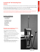
Operation of your Lock-N-Load® Auto Progressive Press The Hornady Lock-N-Load® AP™ utilizes a high strength aluminum alloy frame with a compound linkage system which operates the 2" diameter cylindrical ram. The Ram houses a drive shaft that is attached to the shell plate at the upper end and the index wheel at the lower end. The toggle contains two spring actuated pawls which alternately engage the index wheel to advance the shell plate through the different reloading stations.
Installing the Shell Plate • Put a small amount of general-purpose grease on the Shell Plate Ball Detents located on bottom side of Shell Plate (3), and on the top surface of the Sub-Plate (6). 1 – Shell Plate Retainer Bolt • Align the Shell Plate (3) with the keyed Drive Hub (5). • Place the 3/8" Shell Plate Retainer Bolt (1) through the 3/8" Flat Washer (2), (large end up) and thread the bolt into the Drive Hub (5).
Preparing to Load To begin reloading, start with a single empty cartridge case and run it through all of the loading stations. This will allow you to check your adjustments. Refer to instructions provided with the die set for set up and proper adjustment. Sizing a case • Make sure the sizing die is adjusted properly, and the de-priming pin knocks out the old primer. Seating a primer • Check and make sure the Primer Slide picked up a primer from the Primer Tube (large or small).
Adjusting the Auto Advance Mechanism The Auto Advance Mechanism is fully adjusted at the Hornady factory and should not require further adjustment. In the event that you feel your shell plate is not advancing properly, check all other options listed in this manual before attempting to adjust the mechanism’s pawls. All adjustments should be made in extremely small increments. Through everyday use, the pawls on your press may gradually wear and may need to be adjusted to compensate for this wear.
Setup / Changeover of Auto Progressive Reloading Press When changing calibers on the Lock-N-Load® AP™ Press, three components may need to be changed or verified. • Shell plate • Dies • Primer Components Primer Slide Primer Tube Primer Punch Determine which shell plate is required for your application Refer to Appendix A for proper Shell Plate selection. Shell Plate NOTE: Hornady shell plates that are sold in the plastic boxes are the only ones that will fit the AP Press with EZject™ System.
1 Changing Primer Components When changing from a large primer to a small primer (or vice versa), you need to change the Primer Feed Tube Primer Slide and Punch Assembly. 1 Primer Feed Tube Primer Slide Punch Assembly 2 If there are primers in the Primer Feed Tube, you will need to empty it before changing the tubes. If the Primer Feed Tube is already empty, skip to next step.
Setup / Changeover of Powder Measure When changing cartridges, three components on the Powder Measure may need to be changed or verified. • Powder type in the hopper. • Metering Insert and/or Metering Rotor • Powder Sleeve or PTX Expander 1 Emptying Powder in Hopper NOTE: The Lock-N-Load® Powder Measure should be emptied of all powder prior to storage. Prolonged exposure to powder may cause the plastic tube to become cloudy, discolored, or even brittle.
Changing Powder Sleeve or PTX Expander As a general rule, rifle cartridge cases will use either the #1 or #2 Powder Sleeve. Pistol cases will need to use the PTX sleeves when the Hornady Lock-N-Load® Bullet Feeder is being used. Otherwise the Universal Pistol Powder Sleeve will be used. Refer to the chart below to select the proper Sleeve or Expander. Remove spring, PTX Stop and loosen thumb screw. Remove Powder Measure body from lower assembly. Turn lower assembly over so powder sleeve drops out.
Adjusting the PTX Stop Metering Inserts should not contact Powder Measure Body Place Powder Measure Assembly onto the Lock-N-Load® AP™ Press in the proper station. Remove PTX Spring and Stop from Powder Measure. Insert a case into the shell plate under the powder measure and operate the handle to raise the ram to its highest position.
CHANGE-OVER 5 Holding the PTX Powder Measure Stop, unscrew one of the cap screws until the threaded end of the screw is flush with the inside of the slot. 5 6 Unscrew the other cap screw until approximately two threads are showing. 6 7 Install the PTX Powder Measure Stop over the hex spring mount with the cap screw that is protruding on the top.
8 Place an empty, primed case into the station of the shell plate that will rotate to the powder measure. Raise the ram which will cycle the powder measure to the top of its stroke. Thread the bottom cap screw in until the threaded end bottoms out on the lower hex spring mount. 9 Lower the ram and replace the vertical spring on the hex spring mount. 9 To adjust for more case mouth flare, continue to screw in the bottom cap screw, for less case mouth flare, back it out. Make small adjustments.
Troubleshooting the Lock-N-Load® Ammo Plant Tips for Trouble-Free Operation of the Lock-N-Load® AP™ Press Problems Solutions Powder dropping around case • Correct bushing in place? • Powder drop tube and measure adapter clean? • Bushing installed deep counter sink side up? No primer in case • • • • • • Shell Plate will not advance or does not index on station • Primer not fully seated? • Pawls correctly adjusted? • Make sure you have the latest shell plate version with the groove on the bottom side.
APPENDIX A 046202 044101 046200 044101 046201 044101 — — — — 046206 044139 046208 044139 046590 044139 046213 044102 — — 046212 044136 — — 046211 044102 046225 044102 046229 044102 544229 044102 — — — — — — 046233 044127 — — 046221 044102 — — 046223 044127 — — 046558 044707 046238 044127 — — — — — — — — — — — — — — 544255 — — — — — 544251 — — — — — 046245 044103 046247 044103 — — — — 046557 — — — — — — — 046276 044104 — — 046275 044104 — — 046263 044104 — — 046277 044104 — — — — 046598 044164 046291 044106
APPENDIX A - 28 - .264 .264 .264 .268 .277 .277 .277 .277 .277 .284 .284 .284 .284 .284 .284 .284 .284 .284 .284 .284 .284 .284 .284 .284 .284 .284 .284 .284 .284 .284 .300 .308 .308 .308 .308 .308 .308 .308 .308 .308 .308 .308 .308 .308 .308 .308 .308 .308 .308 .308 .308 .308 .308 .308 .308 .308 .308 .308 .308 .308 .308 .308 .308 — .311 .312 .312 .
APPENDIX A — — — 046376 046383 046377 — — — — — — — — 046595 046597 — — 046594 046391 — 046446 046593 — — 046399 — — — 046401 — 046411 046415 046413 — — — — 046417 046418 — — — 046456 — — — — — — — 046552 046422 046424 046567 046587 — 046570 046457 — — — — — — — — — 044137 044116 044116 — — — — — — — — 044131 044131 — — 044131 044117 — 044117 044117 — — 044130 — — — 044119 — 044120 044120 044120 — — — — 044121 044121 — — — 044162 — — — — — — — 044149 044721 044190 044152 044152 — 044153 044153 — — — — — —
APPENDIX A APPENDIX A - 30 - 546218 — 546336 — 546506 — — — — 046507 — — — — 044113 — — — — 044508 — — — — — — — — — — Primer Punch Trimme # / Item r Pilot No. Case Feeder Size / It Plate em No.
APPENDIX B - TEMPLATE Lock-N-Load® AP™ (optional accessory) APPENDIX B
780307A P.O. Box 1848, Grand Island, Nebraska 68802-1848 308-382-1390 • 800-338-3220 • Fax: 308-382-5761 www.hornady.com • webmaster@hornady.