
Product Manual


311-0288-020
REV. C 12/02
RECOMMENDED LOCATION
FOR ERROR CODE LABEL
EMPLACEMENT RECOMMANDÉ POUR
L’ÉTIQUETTE DE CODE D’ERREUR
LOCALIZACIÓN RECOMENDADA PARA LA
ETIQUETA DEL CÓDIGO DE ERRORES
MANUAL OVERRIDE SLIDE
INTERRUPTEUR PRIORITAIRE MANUEL À
GLISSIÈRE
DESLIZADERA MANUAL DE TRASLAPE
PLUG-IN SIMPLE™ CONNECTION
CONNEXION PLUG-IN SIMPLE™
CONEXIÓN PLUG-IN SIMPLE™
RED “SMART” LED FOR TRAILER SHORTS
VOYANT « INTELLIGENT » ROUGE POUR
COURTS-CIRCUITS DE REMORQUE
FOCO ROJO “INTELIGENTE” PARA CORTOS EN
REMOLQUE
BI-COLORED LED POWER DISPLAY
AFFICHEUR DE PUISSANCE À VOYANT BICOLORE
FOCO BI-COLOR INDICATOR DE POTENCIA
POWER ADJUSTMENT
WHEEL
ROULETTE DE RÉGLAGE
DE PUISSANCE
RUEDA DE AJUSTE ENERGÍA
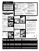
Package should include: 4 screws, bracket,
splice, instruction sheet and brake control unit.
Le paquet doit comprendre : 4 vis, un support, un raccord,
des directives et l’appareil de commande de frein.
Paquete debe incluir: cuatro tornillos, soporte, empalme,
hoja de instrucciones y unidad de control de freno.
B
RAKE-
F
ORCE
TM
Electronic Brake Control Instructions
Directives pour la Commande
Électronique de frein
Instrucciones para el Control de
Frenos Electrónico
IMPORTANT: Completely Read All Instructions Before
Installing This Brake Control.
PLUG-IN SIMPLE™ INSTALLATIONS
Vehicles that come with a factory tow package
can simplify wiring
by using plug-in simple™ connectors. Hopkins offers connectors
for the listed vehicles below. Check with your nearest Hoppy
®
dealer for availability (or call 1-800-835-0129 for a dealer near you).
FORD VEHICLES
Part No. 37695 / 47695
Pickups 1992-93
Part No. 37705 / 47705
F-Series Pickups
(F-150, F-250,
F-350) 1994-02
Expedition 1997-01
Excursion 1999-02
Full Size Van 1994-98
The location of the vehicle
connector for 1994-96 F-Series
Pickups can be found at the
arrow marked “B”. All other applications listed can be located at
the arrow marked “A” (Fig. 1, Fig. 2) .
Plug-In Simple™ Connector Instructions
1. Plug the Hoppy
®
connector into the vehicle connector located
under dash.
2. Connect wires coming from the plug-in simple™ harness with
the corresponding wires coming from the brake controller.
3. Test all Functions.
GM VEHICLES
Part No. 37785 / 47785
Silverado 1999-02
Sierra 1999-02
Suburban 2000-02
Tahoe 2000-02
Yukon 2000-02
Denali 2000-02
Escalade 2000-02
ENGLISH
ELECTRONIC FILE ONLY
Vehicle Connector
Hoppy
®
Connector
FIG. 2
FIG. 1
A
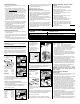
1. Locate the black junction box underneath the dash on the left
side of the brake pedal (Fig. 3 / A).
2. Loosen and remove the nut located in the center of the box
and remove cover (Fig. 4 / A).
3. Plug the connector into the second port in the top left hand
corner of the junction box (Fig. 5 / A).
4. Connect wires coming from the plug-in simple™ harness with
the corresponding wires coming from the brake controller.
5. Test all Functions
CHRYSLER VEHICLES
Part No. 37745 / 47745
Ram Pickups 1997-02
Durango 1998-02
Dakota 1997
1. Locate 4-pin blade connector under vehicle dash on the left
side of the steering column (Fig. 6 / A).
Part No. 37785 / 47785
Continued
FIG. 4
FIG. 5
A
A
Vehicle Connector
Hoppy
®
Connector
FIG. 6
A
2. Plug the Hoppy
®
connector into the vehicle connector.
3.
Connect wires coming from the plug-in simple™ harness with
the corresponding wires coming from the brake controller.
4. Test all functions.
For vehicles without the vehicle tow package, follow the universal
instructions below.
UNIVERSAL INSTALLATION
Color Code: White Wire... Ground
Blue Wire..... Trailer electric brakes
Black Wire... Positive terminal on battery
Red Wire..... Cold side of stop lamp switch
1. Be sure to use proper wire gauge when installing your
control (12 gauge for electric brakes, power and ground / 14
gauge for the stoplight switch).
2. Connect white wire to negative post on the vehicle battery.
Grounding to any other location may cause intermittent
brake control operation or failure.
3. Attach 30 amp circuit breaker or in-line fuse to the positive
terminal on the vehicle’s battery. Route black wire from the
brake control to the fuse or breaker.
4. Splice red wire into cold side of vehicle’s stoplight switch
located by the brake pedal. Find the wire by using a circuit
tester and probing for the wire that powers the vehicle
stoplights when the brake pedal is pressed.
5. Route blue wire from brake control to vehicle side trailer
connector.
6. Plug harness into back of control.
IMPORTANT: Please see “vehicle specific
instructions” and “special notes” before every
installation.
© 1995 Hopkins Manufacturing Corporation
Printed in U.S.A.
Continued On Reverse Side
FIG. 3
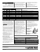
YEAR
WIRE LOCATION
MODEL
VEHICLE STOP LIGHT SWITCH
WIRE COLOR
MAKE
VEHICLE SPECIFIC INSTRUCTIONS
1989 – 91 Ford E & F-Series Light Green Located in C-shaped connector on steering column; 2nd pin on the top row of 7.
1992 – 93 Ford F-Series Light Green 4-pin connector in center of vehicle under dash.
1992 – 93 Ford E-Series Light Green with Red Stripe 4-pin connector next to brake pedal.
1994 – 99 Ford E & F-Series Light Green Under dash to the right of the steering column.
1997 – 02 Ford Expedition & Navigator Light Green Under dash to the right of the steering column.
1988 – 93 GM Pickups White Under dash near top of brake pedal.
1994 GM Pickups Yellow Under dash near top of brake pedal.
1995 – 96 GM Pickups & SUV’s White Connector on left of steering column. There are several white wires in this connector.
The correct wire is located in position “F”.
1988 – 93 Chrysler Pickups White Under dash near top of brake pedal.
1994 – 95 Chrysler Pickups White with Brown Stripe Under dash near top of brake pedal.
1996 – 02 Chrysler Pickups & SUV’s White with Brown Stripe Under dash to the left of the steering column.
1988 – 90 Jeep All Light Blue with Black Stripe Under dash near top of brake pedal.
1991 – 93 Jeep All White with Brown Stripe Under dash near top of brake pedal.
1994 – Present Jeep All CONTACT YOUR JEEP DEALER.