
Owners manual

+
–
J
G
E
H
D
F
B
C
G
G
I
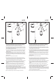
1. Use the blue butt splice (E) to connect the red wire (A) to the stop
lamp switch lead on the brake control. Connect the other end of red
wire to the stop lamp switch in the vehicle using the splice connector
(F).
2. Use a yellow butt splice (G) to connect the blue wire (B) to the trailer
brake lead on the brake control. Route the other end of the blue wire
to the trailer connector (H) at the back of the vehicle.
3. Use a yellow butt splice (G) to connect the white wire (D) to the
ground lead on the brake control. Route the other end of the white
wire to the vehicle’s battery. Use the ring connector (I) to connect the
white wire to the battery’s negative terminal.
4. Use a yellow butt splice (G) to connect the black wire (C) to the
power lead on the brake control. Route the other end of the black
wire to the vehicle’s battery. Use the fuse assembly (J) to connect the
black wire to the battery’s positive terminal.
5. Use zip ties to secure loose wires as needed.
_______________________________________________________________
1. Use la union butt azul (E) para conectar el cable rojo (A) a la terminal
del switch del foco del frenos. Conecte el otro extremo del cable rojo
al switch del foco del freno del vehiculo usando el conector de union
(F).
2. Use una union butt amarilla (G) para conectar el cable azul (B) a la
terminal del freno del remolque en el control de frenos. Dirija el otro
extremo del cable azul hacia el conector del remolque (H) en la parte
trasera del vehiculo.
3. Use una union butt amarilla (G) para conectar el cable blanco (D) a
la terminal de tierra en el control de frenos. Dirija el otro extremo del
cable blanco hacia la bateria del vehiculo. Use el conector de anillo
(I) para conectar el cable blanco a terminal negativa de la bateria.
4. Use una union butt amarilla (G) para conectar el cable negro a la
terminal de corriente en el control de frenos. Dirija el otro extremo del
cable negro (C) a la bateria del vehiculo. Use el ensample de fusible
(J) para conectar el cable negro a la terminal positiva de la bateria.
5. Use las corbatas para asegurar cables sueltos segun sea necesario.
A
#47275
+
–
J
G
E
H
D
F
B
C
G
G
I
1. Use the blue butt splice (E) to connect the red wire (A) to the stop lamp
switch lead on the brake control. Connect the other end of red wire to the
stop lamp switch in the vehicle using the splice connector (F).
2. Use a yellow butt splice (G) to connect the blue wire (B) to the trailer brake
lead on the brake control. Route the other end of the blue wire to the trailer
connector (H) at the back of the vehicle.
3. Use a yellow butt splice (G) to connect the white wire (D) to the ground lead
on the brake control. Route the other end of the white wire to the vehicle’s
battery. Use the ring connector (I) to connect the white wire to the battery’s
negative terminal.
4. Use a yellow butt splice (G) to connect the black wire (C) to the power lead
on the brake control. Route the other end of the black wire to the vehicle’s
battery. Use the fuse assembly (J) to connect the black wire to the battery’s
positive terminal.
5. Use zip ties to secure loose wires as needed.
_______________________________________________________________
1. Use la union butt azul (E) para conectar el cable rojo (A) a la terminal del
switch del foco del frenos. Conecte el otro extremo del cable rojo al switch
del foco del freno del vehiculo usando el conector de union (F).
2. Use una union butt amarilla (G) para conectar el cable azul (B) a la terminal
del freno del remolque en el control de frenos. Dirija el otro extremo
del cable azul hacia el conector del remolque (H) en la parte trasera del
vehiculo.
3. Use una union butt amarilla (G) para conectar el cable blanco (D) a la
terminal de tierra en el control de frenos. Dirija el otro extremo del cable
blanco hacia la bateria del vehiculo. Use el conector de anillo (I) para
conectar el cable blanco a terminal negativa de la bateria.
4. Use una union butt amarilla (G) para conectar el cable negro a la terminal de
corriente en el control de frenos. Dirija el otro extremo del cable negro (C) a
la bateria del vehiculo. Use el ensample de fusible (J) para conectar el cable
negro a la terminal positiva de la bateria.
5. Use las corbatas para asegurar cables sueltos segun sea necesario.
A
+
–
J
G
E
H
D
F
B
C
G
G
I
1. Use the blue butt splice (E) to connect the red wire (A) to the stop
lamp switch lead on the brake control. Connect the other end of red
wire to the stop lamp switch in the vehicle using the splice connector
(F).
2. Use a yellow butt splice (G) to connect the blue wire (B) to the trailer
brake lead on the brake control. Route the other end of the blue wire
to the trailer connector (H) at the back of the vehicle.
3. Use a yellow butt splice (G) to connect the white wire (D) to the
ground lead on the brake control. Route the other end of the white
wire to the vehicle’s battery. Use the ring connector (I) to connect the
white wire to the battery’s negative terminal.
4. Use a yellow butt splice (G) to connect the black wire (C) to the
power lead on the brake control. Route the other end of the black
wire to the vehicle’s battery. Use the fuse assembly (J) to connect the
black wire to the battery’s positive terminal.
5. Use zip ties to secure loose wires as needed.
_______________________________________________________________
1. Use la union butt azul (E) para conectar el cable rojo (A) a la terminal
del switch del foco del frenos. Conecte el otro extremo del cable rojo
al switch del foco del freno del vehiculo usando el conector de union
(F).
2. Use una union butt amarilla (G) para conectar el cable azul (B) a la
terminal del freno del remolque en el control de frenos. Dirija el otro
extremo del cable azul hacia el conector del remolque (H) en la parte
trasera del vehiculo.
3. Use una union butt amarilla (G) para conectar el cable blanco (D) a
la terminal de tierra en el control de frenos. Dirija el otro extremo del
cable blanco hacia la bateria del vehiculo. Use el conector de anillo
(I) para conectar el cable blanco a terminal negativa de la bateria.
4. Use una union butt amarilla (G) para conectar el cable negro a la
terminal de corriente en el control de frenos. Dirija el otro extremo del
cable negro (C) a la bateria del vehiculo. Use el ensample de fusible
(J) para conectar el cable negro a la terminal positiva de la bateria.
5. Use las corbatas para asegurar cables sueltos segun sea necesario.
A
#47275
+
–
J
G
E
H
D
F
B
C
G
G
I
1. Use the blue butt splice (E) to connect the red wire (A) to the stop lamp
switch lead on the brake control. Connect the other end of red wire to the
stop lamp switch in the vehicle using the splice connector (F).
2. Use a yellow butt splice (G) to connect the blue wire (B) to the trailer brake
lead on the brake control. Route the other end of the blue wire to the trailer
connector (H) at the back of the vehicle.
3. Use a yellow butt splice (G) to connect the white wire (D) to the ground lead
on the brake control. Route the other end of the white wire to the vehicle’s
battery. Use the ring connector (I) to connect the white wire to the battery’s
negative terminal.
4. Use a yellow butt splice (G) to connect the black wire (C) to the power lead
on the brake control. Route the other end of the black wire to the vehicle’s
battery. Use the fuse assembly (J) to connect the black wire to the battery’s
positive terminal.
5. Use zip ties to secure loose wires as needed.
_______________________________________________________________
1. Use la union butt azul (E) para conectar el cable rojo (A) a la terminal del
switch del foco del frenos. Conecte el otro extremo del cable rojo al switch
del foco del freno del vehiculo usando el conector de union (F).
2. Use una union butt amarilla (G) para conectar el cable azul (B) a la terminal
del freno del remolque en el control de frenos. Dirija el otro extremo
del cable azul hacia el conector del remolque (H) en la parte trasera del
vehiculo.
3. Use una union butt amarilla (G) para conectar el cable blanco (D) a la
terminal de tierra en el control de frenos. Dirija el otro extremo del cable
blanco hacia la bateria del vehiculo. Use el conector de anillo (I) para
conectar el cable blanco a terminal negativa de la bateria.
4. Use una union butt amarilla (G) para conectar el cable negro a la terminal de
corriente en el control de frenos. Dirija el otro extremo del cable negro (C) a
la bateria del vehiculo. Use el ensample de fusible (J) para conectar el cable
negro a la terminal positiva de la bateria.
5. Use las corbatas para asegurar cables sueltos segun sea necesario.
A