
Owners manual
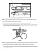
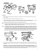
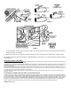

Figure D Figure E
RIGHT SIDE
1. Remove the air conditioning compressor (if equipped), generator/alternator (if mounted on right side), spark plugs, and stock
exhaust manifold.
2. Remove, modify, and replace the rocket panel molding. See Figure A or B.
3. If generator/alternator was mounted on the exhaust manifold, purchase Hooker bracket P/N 10927HKR, to reinstall. See Figure D.
If the header is equipped with smog bushings, the bracket must be notched to clear the bushings. See Figure E.
4. If equipped with air conditioning, purchase Hooker bracket P/N 10926HKR to reinstall.
NOTE: On 1963-64 models with factory air conditioning and compressor mounted on the right-side exhaust manifold, Hooker air
conditioner bracket P/N 10926HKR will not work. It will be necessary to purchase Hooker generator/alternator bracket P/N
10922HKR and modify it, if the air conditioner compressor is to be retained.
NOTE: Trim the bracket as shown in Figure F, using the bolts supplied with the bracket. Attach to the right-side cylinder head over
the #1 header tube. Bolt the stock air conditioner bracket with the compressor attached to the Hooker bracket, using two 3/8-
16 nuts and bolts. Remove one bolt attaching the water pump housing to the right side of the engine block. Fabricate a
spacer approximately 1” long to go between the water pump housing and the stock air conditioner bracket. Align the pulley on
the air conditioner with the appropriate drive pulley on the crankshaft by sighting down the V-belt. Some adjustment in the
spacer length may be required. After all components are aligned, install a bolt of sufficient length to hold the air conditioner
bracket, spacer, and water pump housing to the engine block. Tighten all bolts and nuts securely. See Figure G.
Figure F Figure G
5. 1977 models employ a different type of bracket to remount the air conditioning compressor. Replace the long stock stud in the
front bolt hole of the flange. Fabricate a spacer (3/8” ID x 1/4” long, approximately 5/8” OD) and install the compressor according
to Figure H.
6. If the vehicle has a smog air pump connected to the stock exhaust system, it will be necessary to fabricate (2) adapters
approximately 1 1/2” long from a piece of 5/8” OD tubing. Weld one tubing stub (drill hole before welding) to the R-3 header pipe
on the right side to the collector or a header pipe on the left side. See Figures I and J. Cut the tubing from the air pump about six
inches from the lower end using 5/8” ID neoprene smog hose. Connect the right side stub (on R-3) to the air pump with the “T” in
the line. Connect the left side tube to the “T” fitting. Secure with hose clamps. See Figure J.
3