Excel 10 W7761A Remote Input/Output Device CONTENTS Table of Contents Introduction ........................................................................................................................... Description of Devices ....................................................................................... Control Application ............................................
EXCEL 10 W7761A INPUT/OUTPUT DEVICE Fig. 5. DIN rail adapters..................................................................................... 12 Fig. 6. T7770A,B,C,D construction (T7770A,C shown). .................................... 15 Fig. 7. T7780 construction. ................................................................................ 16 Fig. 8. Connecting the portable operator terminal to the E-Bus. ....................... 18 Fig. 9.
EXCEL 10 W7761A INPUT/OUTPUT DEVICE INTRODUCTION Description of Devices The W7761A, Excel 10 Remote Input/Output device, provides auxiliary inputs and outputs for use with an Excel 10 Zone Manager and Excel 10 controllers over the Echelon® LonWorks®E-Bus. These I/O points are configured with the E-Vision tool. The W7761A device uses Echelon® LonWorks® communication technology and a new free topology twisted pair transceiver (FTT) for greater network installation flexibility.
EXCEL 10 W7761A INPUT/OUTPUT DEVICE Control Application The W7761A, Excel 10 Remote Input/Output device, provides auxiliary inputs and outputs for use with an Excel 10 Zone Manager and Excel 10 controllers over the Echelon® LonWorks®E-Bus. The W7761A Remote Input/Output Device can be connected to outdoor air temperature and humidity sensors that can be used by other Excel 10 controllers on the E-Bus or Excel 5000 controllers on the C-Bus through the Excel 10 Zone Manager.
EXCEL 10 W7761A INPUT/OUTPUT DEVICE 74-2698 74-2956 74-2697 74-2955 74-2950 74-2952 74-2954 74-2858 Excel 10 W7761A Device Specification Data Excel 10 W7750A,B Controller Specification Data T7770A through G Wall Module Specification Data T7780 Digital Display Wall Module Specification Data Excel 10 Q7750A, Zone Manager Specification Data Excel 10 Q7751A Router Specification Data Excel 10 Q7752A Serial Interface Specification Data Excel 10 Q7740A,B FTT Repeaters Specification Data 95-7539 95-7521 95-7538 9
EXCEL 10 W7761A INPUT/OUTPUT DEVICE Agency Listings Table 1 provides information on agency listings for Excel 10 products. Table 1. Agency Listings. Device W7761A Input/Output Device Agency Comments UL Tested and listed under UL916 (file number E87741). cUL Listed (E87741). CE General Immunity per European Consortium Standards EN50081-1 (CISPR 22, Class B) and EN 50082-1:1992 (based on Residential, Commercial, and Light Industrial). EN 61000-4-2: IEC 1000-4-2 (IEC 801-2) Electromagnetic Discharge.
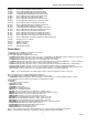
EXCEL 10 W7761A INPUT/OUTPUT DEVICE DDF - Delta Degrees Fahrenheit. D/X - Direct Expansion; refers to a type of mechanical cooling where refrigerant is (expanded) to its cold state, within a heat-exchanging coil that is mounted in the air stream supplied to the conditioned space. E-Bus - Honeywell implementation of Echelon® LonWorks® network for communication among Excel 10 Controllers. E-Bus Segment - An E-Bus section containing no more than 60 Excel 10s.
EXCEL 10 W7761A INPUT/OUTPUT DEVICE PWM - Pulse Width Modulated output; allows analog modulating control of equipment using a digital output on the controller. RTD - Resistance Temperature Detector; refers to a type of temperature sensor whose resistance output changes according to the temperature change of the sensing element. RIO - Remote Input/Output Device. Provides auxiliary inputs and outputs for use with an Excel 10 Zone Manager and Excel 10 controllers.
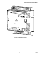
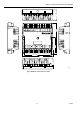
EXCEL 10 W7761A INPUT/OUTPUT DEVICE W 7761A 31 DI - 4 EGND 1 30 G ND NOT USED 2 29 DI-3 NOT USED 3 28 DI-2 AI-1 OHM 4 27 G ND GND 5 26 D I- 1 AI-2 OHM 6 25 VAC 2 4 AI-3 OHM 7 2 4 23 VAC 2 4 COM GND 8 OU T 1 AI-4 OHM 9 22 OU T 2 AI-5 V/mA 10 21 2 0 O UT 3 GND O UT 4 AI-6 V/mA 11 1 2 19 OU T 5 18 OU T 6 22 V D C O UT 13 17 O UT 7 EB U S 14 15 16 O UT 8 E BU S J AC K J3 M 1 01 18 Fig. 3. Excel 10 W7761A Remote I/O Device.
EXCEL 10 W7761A INPUT/OUTPUT DEVICE 2 -1 /8 (5 4 ) 31 30 29 28 27 26 25 VA C 24 24 23 VA C 24 CO M 22 21 20 19 OU T 1 OU T 2 O UT 3 O UT 4 O UT 5 D I- 4 GND D I- 3 D I-2 GND D I- 1 EGND NOT USED NOT USED AI-1 OHM GND AI-2 OHM AI-3 OHM GND AI-4 OHM AI-5 V/mA GND AI-6 V/mA 22 VDC O UT 2 3 4 5 6 7 8 9 10 11 12 13 1 18 17 O UT 6 OU T 7 E BU S 14 15 16 O UT 8 EB U S J AC K J3 5 -5 /8 (1 43 ) 3 -1 /1 6 (77 ) 5 -3 /1 6 (1 3 2 ) 6 (1 5 2 ) M 68 5 6 Fi
EXCEL 10 W7761A INPUT/OUTPUT DEVICE 2 3 1 M6857 Fig. 5. DIN rail adapters. The input/output points are summarized in Table 2. Table 2. List Of Available Points. W7761A Digital Outputs 8 Triac Outputs Digital Inputs 4 Analog Inputs 6 (4 Resistive and 2 Voltage/Current Inputs) DC Power 20 Vdc available to power optional sensors (50 mA max.
EXCEL 10 W7761A INPUT/OUTPUT DEVICE CPU: Motorola or Toshiba 3150 Neuron processor, containing three eight-bit CPU’s. Each Neuron has a unique 48-bit network identification number. Memory Capacity: 64K ROM/PROM (6K reserved for network operations, 58K usable for control algorithm code). 512 bytes EEPROM. 2K RAM.
EXCEL 10 W7761A INPUT/OUTPUT DEVICE Supported Sensors: T7770A,B,C,D sensor—(current feature that can be used with the RIO Device) and T7780 DDWM. Discharge Air Temperature: Type: RTD. Supported Sensors: C7100A1015*, C7770A1006, C7031B1033, C7031C1031, C7031D1062, C7031J1050, C7031K1017. Outdoor Air Temperature: Type: RTD. Supported Sensors: C7170A1002. Return Air Temperature: Type: RTD. Supported Sensors: C7100A1015*, C7770A1006, C7031B1033, C7031C1031, C7031D1062, C7031J1050, C7031K1017.
EXCEL 10 W7761A INPUT/OUTPUT DEVICE CAUTION When any device is energized by a Triac, the device must be able to sink a minimum of 25 mA. NOTE: Triacs sink current to the 24 Vac common (COM terminal on the W7761A); see Fig. 19 for wiring example. IMPORTANT: If non-Honeywell motors, actuators, or transducers are to be used with Excel 10 Controllers, Triac compatibility must be verified (see previous NOTE).
EXCEL 10 W7761A INPUT/OUTPUT DEVICE The T7780 DDWM for the Excel 10 Controllers (see Product Names section) is shown in Fig. 7. KNOCKOUTS FOR EUROPEAN APPLICATIONS 5-1/16 (128) 1 (25) 3-5/32 (80) 2-3/8 (60) 2-3/8 (60) STANDARD UTILITY CONDUIT BOX (2 X 4) MOUNTING HOLES M11391 Fig. 7. T7780 construction, subbase dimensions in in. (mm). Configurations Each W7761A device can control or monitor a variety of different types of mechanical equipment.
EXCEL 10 W7761A INPUT/OUTPUT DEVICE average many space temperature sensors that are located in a zone that is controlled by the W7750 Constant Volume AHU Controller. Mixed-Output-Type Control The W7761A Device can control mixed-output-types of applications such as PWM and staged control occurring simultaneously with Series 60 Floating Control. Occupancy Sensor Excel 10 W7761A device can be connected to an occupancy sensor through a digital input.
EXCEL 10 W7761A INPUT/OUTPUT DEVICE APPLICATION STEPS Overview The seven application steps shown in Table 3 are planning considerations for engineering an Excel 10 W7761 Remote Input/Output Device. These steps are guidelines intended to aid understanding of the product I/O options, bus arrangement choices and the Excel 10 W7761A Devices role in the overall EXCEL 5000® System architecture. Table 3 . Application Steps. Step No.
EXCEL 10 W7761A INPUT/OUTPUT DEVICE It is important to understand these interrelationships early in the job engineering process to ensure implementing when configuring the controllers. (See Application Step 6. Configure Devices, for information on the various Excel 10 parameters and on Excel 10 point mapping.) Step 2. Determine Other Bus Devices Required A maximum of 62 nodes can communicate on a single E-Bus segment.
EXCEL 10 W7761A INPUT/OUTPUT DEVICE NOTE: For wiring details see the E-Bus Termination Module subsection in Step 4. For wall module wiring, US part AK3782 (non-plenum) or US part AK3792 (plenum) can be used. These cables contain two twisted pairs (one for the run down to the wall module, and one for the run back up to the controller) for ease of installation.
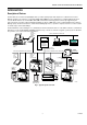
EXCEL 10 W7761A INPUT/OUTPUT DEVICE ( %86 6(*0(17 180%(5 (;&(/ 9$9 (;&(/ (;&(/ 5,2 89 % % 7(50,1$7,21 7(50,1$7,21 02'8/( 02'8/( 7 ( %86 6(*0(17 180%(5 ( %86 $&&(66 (;&(/ 9$9 (;&(/ 4 $ )77 =21( 0$1$*(5 (;&(/ 9$9 72 & %86 6(( ),* 4 $ )77 ( %86 5287(5 ( %86 6(*0(17 180%(5 (;&(/ (;&(/ (;&(/ 89 5,2 7 89 0 -' ( %86 $&&(66 Fig. 10. Bus wiring layout for two singly terminated E-Bus segments.
EXCEL 10 W7761A INPUT/OUTPUT DEVICE ML6161 Damper Actuator 2.2 VA R8242A Contactor for fan 21.0 VA TRADELINE® Catalog TRADELINE® Catalog in-rush rating M6410A Steam 0.7 VA TRADELINE® Heating Coil Valve Catalog, 0.32A at 24 Vac TOTAL: 29.9 VA The Excel 10 System example requires 29.9 VA of peak power; therefore, a 40 VA AT72D Transformer is able to provide ample power for this device and its accessories.
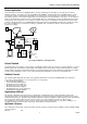
EXCEL 10 W7761A INPUT/OUTPUT DEVICE No installation should be designed where the line loss is greater than two volts to allow for nominal operation if the primary voltage drops to 102 Vac (120 Vac minus 15 percent). To meet the National Electrical Manufacturers Association (NEMA) standards, a transformer must stay within the NEMA limits. The chart in Fig. 11 shows the required limits at various loads.
EXCEL 10 W7761A INPUT/OUTPUT DEVICE TRANSFORMER 120/240 VAC 24 VAC W7761A W7761A 25 24 W7761A 25 24 1 25 24 1 EARTH` GROUND 1 EARTH` GROUND EARTH` GROUND M10090 Fig. 13. Power wiring details for two or more Excel 10s per transformer. IMPORTANT If the W7761A Device is used on Heating and Cooling Equipment (UL 1995 US only) devices and the transformer primary power is more than 150 volts, connect the transformer secondary to earth ground, see Fig. 14.
EXCEL 10 W7761A INPUT/OUTPUT DEVICE • Make earth ground connections with the shortest possible wire run using 14 AWG (2.0 mm2) wire. A good earth ground is essential for W7761A operation. Ideally, connect the earth ground to the ground bus at a motor control center or circuit breaker panel. However, if the nearest ideal earth ground is inaccessible, consider an alternate source for earth ground. Metal water pipe is generally a good ground, but do not use sprinkler pipe if prohibited by local codes.
EXCEL 10 W7761A INPUT/OUTPUT DEVICE TWO 14 AWG` (2.0 MM2 ) WIRES 3/8` (10) 1. STRIP 3/8 IN. (10 MM) FROM WIRES ` TO BE ATTACHED AT ONE TERMINAL. 2. TWIST WIRES TOGETHER ` WITH PLIERS (A MINIMUM ` OF THREE TURNS). 3. CUT TWISTED END OF WIRES TO 3/16 IN. (5 MM) ` BEFORE INSERTING INTO TERMINAL AND TIGHTENING` SCREW. THEN PULL ON EACH WIRE IN ALL TERMINALS` TO CHECK FOR GOOD MECHANICAL CONNECTION. M10086 Fig. 15. Attaching two or more wires at terminal blocks.
EXCEL 10 W7761A INPUT/OUTPUT DEVICE GROUND 5 Analog ground AI-1 4 Analog Input 1 resistance 3 Not Used 2 Not Used 1 Earth Ground EGND See Fig. 20 to wire a pneumatic transducer to a W7761A.
EXCEL 10 W7761A INPUT/OUTPUT DEVICE + 24 VA C 17 16 O UT 7 18 O UT 8 19 O UT 6 20 O UT 5 O UT 1 E-BUS 11 12 13 14 1 E-BUS JACK 22 VDC OUT 10 GROUND 9 AI-6 V/ mA 8 AI-5 V /mA 7 GROUND 6 AI-4 OHM 5 AI-3 OHM 4 3 GR O U N D 2 AI-2 OHM AI- 1 OHM EARTH G ROUND 1 21 TRI AC EQUIV AL ENT CIRCUIT W 7 761 A RE M O T E I/O DE V IC E NOT US ED 22 O UT 3 23 O UT 4 24 O UT 2 25 24 VAC 26 DI-1 27 GROUND 28 DI-2 29 DI-3 30 G ROUND DI-4 31 24 VA C COM - 15 J3 2 E-B
EXCEL 10 W7761A INPUT/OUTPUT DEVICE WINDOW CONTACT (CONTACT CLOSED = WINDOW CLOSED) OCCUPANCY SENSOR (CONTACT CLOSED = OCCUPIED) + - DI-1 18 17 OUT 7 GND 16 GND AI-4 OHM AI-5 V/mA GND AI-6 V/mA 22 VDC OUT 5 6 7 8 9 10 11 12 13 E-BUS 14 15 E-BUS JACK AI-3 OHM AI-1 OHM 19 GND NOT USED 4 20 AI-2 OHM NOT USED 3 21 OUT 8 DI-2 E GND 2 22 TRIAC EQUIVALENT CIRCUIT W7761A REMOTE I/O DEVICE 1 23 OUT 6 DI-3 24 OUT 5 DI-4 25 OUT 4 26 OUT 3 27 OUT 2 28 OUT 1
EXCEL 10 W7761A INPUT/OUTPUT DEVICE PWM VALVE ACTUATOR 24 (H) 24 (N) PWM (H 24 VAC) PWM OUTPUT FROM CNTRL ML7984B T6 T5 C B LINE POWER W R + - FAN 24 VAC DI-1 21 20 19 18 17 OUT 7 GND 22 16 OUT 8 DI-2 23 OUT 6 DI-3 24 OUT 5 DI-4 25 OUT 4 26 OUT 3 27 OUT 2 28 OUT 1 29 24 VAC 30 24 VAC COM 31 GND CONTACTOR (24 VAC) E GND NOT USED NOT USED AI-1 OHM GND AI-2 OHM AI-3 OHM GND AI-4 OHM AI-5 V/mA GND AI-6 V/mA 22 VDC OUT 1 2 3 4 5 6 7 8 9 10 11
EXCEL 10 W7761A INPUT/OUTPUT DEVICE MMC325 PNEUMATIC TRANSDUCER M 2 DECREASE INCREASE 24 (N) 24 (H) 24 (N) 24 (H) M 4 B 1 3 PNEUMATIC VALVE + - DI-1 18 17 OUT 7 GND 16 GND AI-4 OHM AI-5 V/mA GND AI-6 V/mA 22 VDC OUT 5 6 7 8 9 10 11 12 13 E-BUS 14 15 E-BUS JACK AI-3 OHM AI-1 OHM 19 GND NOT USED 4 20 AI-2 OHM NOT USED 3 21 OUT 8 DI-2 E GND 2 22 TRIAC EQUIVALENT CIRCUIT W7761A REMOTE I/O DEVICE 1 23 OUT 6 DI-3 24 OUT 5 DI-4 25 OUT 4 26 OUT 3 2
EXCEL 10 W7761A INPUT/OUTPUT DEVICE W7753A W7753A 1415 BROWN W7753A 1415 1415 ORANGE PART NO. 209541B TERMINATION MODULE PART NO. 209541B TERMINATION MODULE BROWN ORANGE M12690 Fig. 21. Typical E-Bus termination module wiring diagrams (place a wire nut on each remaining wire that is not connected to a controller or device). See Fig. 22 for E-Bus termination wiring options.
EXCEL 10 W7761A INPUT/OUTPUT DEVICE 86( )25 '28%/< 7(50,1$7(' '$,6< &+$,1 6(*0(17 ,17(51$/ 7(50,1$7,21 1(7:25. ,17(51$/ 7(50,1$7,21 1(7:25. : $ 7(50,1$/ %/2&.
EXCEL 10 W7761A INPUT/OUTPUT DEVICE Step 5. Order Equipment After compiling a bill of materials through completion of the previous application steps, refer to Table 8 for ordering information. Contact Honeywell for information about Controllers and Wall Modules with no logo. Table 8. Excel 10 W7761A Device Ordering Information.
EXCEL 10 W7761A INPUT/OUTPUT DEVICE Part Number Table 8. Excel 10 W7761A Device Ordering Information (Continued). Product Description Comments Sensors (Continued): C7031J1050 Averaging Discharge/Return Air Temperature Sensor. 20 Kohm NTC Duct element cord length 12 ft. (3.7m) C7031B1033 Discharge Air or Hot Water Temperature Sensor. 20 Kohm NTC Use 112622AA Immersion Well C7031C1031 Duct Discharge/Return Air Sensor. 20 Kohm 18 in. (457mm) insertion length.
EXCEL 10 W7761A INPUT/OUTPUT DEVICE Table 8. Excel 10 W7761A Device Ordering Information (Continued). Part Number Product Description Comments Accessories (Continued): ML6474A1008 Direct Coupled Actuator, 132 lb-in. torque, Series 60 — ML6185A1000 Direct Coupled Actuator, 50 lb-in.
EXCEL 10 W7761A INPUT/OUTPUT DEVICE Table 8. Excel 10 W7761A Device Ordering Information (Continued). Part Number Product Description Comments Cabling (Continued): Honeywell AK3752 (typical or equivalent) Outputs/Power: 14 to 18 AWG (2.0 to 1.0 mm2) NEC Class 2 140°F (60°C) rating Honeywell AK3702 (typical or equivalent) 18 AWG (1.0 mm2) twisted pair Non-plenum Honeywell AK3712 (typical or equivalent) 16 AWG (1.3 mm2) twisted pair Non-plenum Honeywell AK3754 (typical or equivalent) 14 AWG (2.
EXCEL 10 W7761A INPUT/OUTPUT DEVICE Table 9. Excel 10 Alarms. Alarm type number Name of alarm or error bit Meaning of alarm code or error bit RETURN_TO_NORMAL 128U Return to no alarm after being in an alarm condition. This code is added numerically to another alarm code to indicate that the alarm condition has returned to normal. ALARM_NOTIFY_DISABLED 255U The alarm reporting has been turned off by the DestManMode.
EXCEL 10 W7761A INPUT/OUTPUT DEVICE Table 10. LED States. Alarm Condition None 1. 2. 3. 4. Hardware or Service LED Blink Rate Software Failure (Cycles per second) None 1 Any alarm condition None 2 Don't Care steady ON or OFF Failed Off—no power to the processor. Continuously On—processor is in initialized state. Slow Blink—controlling, normal state. Fast Blink—when the Excel 10 has an alarm condition.
EXCEL 10 W7761A INPUT/OUTPUT DEVICE T7780A BYPASS PUSHBUTTON M11616 Fig. 26. Bypass pushbutton location on T7780 DDWM. APPENDICES Appendix A. Using E-Vision to Commission a W7761 Device. CARE/E-Vision must be used to configure the W7761 device. The inputs and outputs will be configured through the application selection menu (see E-Vision user guide form, 74-2588).
EXCEL 10 W7761A INPUT/OUTPUT DEVICE 2. 3. 4. 5. 6. 7. 8. This procedure will use switching logic to add the pseudo analog point. With the RIO plant having the focus, go into switching logic. Select the Software Points menu item and then Pseudo Analog. The Create/Select Software Point dialog box will be displayed. Type in a New point name for the enthalpy sensor (such as OaEnthaply) and click on the OK button.
EXCEL 10 W7761A INPUT/OUTPUT DEVICE Custom Mapping function. From there it can be used with other Excel 10 controllers (referenced) on the E-Bus, that are used in the Zone Manager control strategy or switching logic, or are used with Excel 5000 controllers on the C-Bus. Table A-1. Supported Voltage And Current Input Sensors.
EXCEL 10 W7761A INPUT/OUTPUT DEVICE 4. 5. 6. 7. 8. displayed. Select the project and the Zone manager within that project that is being exported and the Export button. Exit CARE and Start E-Vision. Select the E-Vision project to open and the CARE Export Filename created previously. Once the project is open, select the RIO device that the Digital Output is connected to and go into the Application Selection screen (offline) by selecting the Controller, Application Selection menu items.
EXCEL 10 W7761A INPUT/OUTPUT DEVICE The T7770A,B,C,D wall module is the room space temperature sensor—(current feature that can be used with the RIO Device). When it is configured, it provides the temperature input that can be shared with the W7750 or W7751 controllers. If there are multiple space sensors in a area controlled by one W7750 CVAHU, then the space temperatures can be wired into the W7761A controller and mapped to the Zone Manager.
EXCEL 10 W7761A INPUT/OUTPUT DEVICE Appendix C. Complete List of Excel 10 W7761A Remote I/O Device User Addresses. C1. Input/Output Points. C2. Control Parameters. C3. Status Points. C4. Configuration Parameters. C5. Direct Access And Special Points. Table C0 lists the applicable Engineering Units for the analog points found in the W7761A. Table C0. Engineering Units For Analog Points.
EXCEL 10 W7761A INPUT/OUTPUT DEVICE Table C1. Input/Output Points (Left). User Address NvName Engineering Units: English (Metric) or States plus Range Field Name Digital State or Value of State Default AI1RType ncirioIoSelect ResistiveIn0 DA_Temp_PT3000 OA_Temp_PT3000 RA_Temp_PT3000 Custom_PT3000 DA_Temp_20KNTC RA_Temp_20KNTC Space_Temp_T7770 Custom_20KNTC Unused_Res_AI AI2RType ncirioIoSelect ResistiveIn1 See AI1RType Eng.
EXCEL 10 W7761A INPUT/OUTPUT DEVICE Table C1. Input/Output Points (Right). Share (SH), Map (MA), Direct Access (DA) E-Vision (EV): Calibrate (C), Monitor (M), Parameter (P), Schematic (S) Hardware Configuration (HW), Manual Point (MN), Test (TS) SH MA DA EV HW MN TS Comments X X AI1RType specifies which logical sensor is assigned to which physical analog input sensor channel according to the enumerated list shown in the Eng. Units/States column.
EXCEL 10 W7761A INPUT/OUTPUT DEVICE Table C1. Input/Output Points (Left Continued).
EXCEL 10 W7761A INPUT/OUTPUT DEVICE Table C1. Input/Output Points (Right Continued). Share (SH), Map (MA), Direct Access (DA) E-Vision (EV): Calibrate (C), Monitor (M), Parameter (P), Schematic (S) Hardware Configuration (HW), Manual Point (MN), Test (TS) SH MA DA EV HW MN TS Comments X X X M DestOut1Cmd: DestOut1Cmd through DestOut8Cmd corresponds to DO1 through DO8. Refer to the Eng. Units/States column for DO1Type for the enumerated values that can be assigned to any output channels.
EXCEL 10 W7761A INPUT/OUTPUT DEVICE Table C1. Input/Output Points (Left Continued). User Address NvName Field Name Engineering Units: English (Metric) or States plus Range Digital State or Value of State Default DI3Sel1Type ncirioIoSelect DigitalIn2S1 See DI1Sel1Type Eng. Units/States column for selections. Unused_DigInput DI4Sel1Type ncirioIoSelect DigitalIn3S1 See DI1Sel1Type Eng. Units/States column for selections.
EXCEL 10 W7761A INPUT/OUTPUT DEVICE Table C1. Input/Output Points (Right Continued). Share (SH), Map (MA), Direct Access (DA) E-Vision (EV): Calibrate (C), Monitor (M), Parameter (P), Schematic (S) Hardware Configuration (HW), Manual Point (MN), Test (TS) SH MA DA EV HW MN TS Comments X X DI3Sel1Type: Refer to the description for DI1Sel1Type. X X DI4Sel1Type: Refer to the description for DI1Sel1Type.
EXCEL 10 W7761A INPUT/OUTPUT DEVICE Table C1. Input/Output Points (Left Continued). User Address NvName Engineering Units: English (Metric) or States plus Range Field Name Digital State or Value of State Default DO2Type ncirioIoSelect DigitalOut1 Refer to the Eng. Units/States column for DO1Type for selections available. Unused_DigOutput DO3Type ncirioIoSelect DigitalOut2 Refer to the Eng. Units/States column for DO1Type for selections available.
EXCEL 10 W7761A INPUT/OUTPUT DEVICE Table C1. Input/Output Points (Right Continued). Share (SH), Map (MA), Direct Access (DA) E-Vision (EV): Calibrate (C), Monitor (M), Parameter (P), Schematic (S) Hardware Configuration (HW), Manual Point (MN), Test (TS) SH MA DA EV HW MN TS Comments X X DO2Type: Refer to the description for DO1Type. X X DO3Type: Refer to the description for DO1Type. X X DO4Type: Refer to the description for DO1Type. X X DO5Type: Refer to the description for DO1Type.
EXCEL 10 W7761A INPUT/OUTPUT DEVICE Table C1. Input/Output Points (Left Continued). User Address SrcDigIn2Sts SrcDigIn3Sts SrcDigIn4Sts NvName Engineering Units: English (Metric) or States plus Range Field Name Digital State or Value of State Default nvoRemoteDigIn(1) DI2Value 0 to 255 0 nvoRemoteDigIn(1) DI2State Refer to the DI1State enumerated list shown in the Eng. Units/States column.
EXCEL 10 W7761A INPUT/OUTPUT DEVICE Table C1. Input/Output Points (Right Continued). Share (SH), Map (MA), Direct Access (DA) E-Vision (EV): Calibrate (C), Monitor (M), Parameter (P), Schematic (S) Hardware Configuration (HW), Manual Point (MN), Test (TS) SH MA DA EV HW MN TS Comments SrcDigIn2Sts: Refer to the description for SrcDigIn1Sts. X X X M DI2State: Refer to the description for DI1State. X X X M DI3State: Refer to the description for DI1State.
EXCEL 10 W7761A INPUT/OUTPUT DEVICE Table C2. Control Parameters (Left).
EXCEL 10 W7761A INPUT/OUTPUT DEVICE Table C2. Control Parameters (Right). Share (SH), Map (MA), Direct Access (DA) E-Vision (EV): Calibrate (C), Monitor (M), Parameter (P), Schematic (S) Hardware Configuration (HW), Manual Point (MN), Test (TS) SH MA DA EV HW MN TS Comments nviInUse is used by a management node to indicate to all other management nodes that it is logged on, to the Excel 10 node and that they should not try to interact with any of the Excel 10s network variables.
EXCEL 10 W7761A INPUT/OUTPUT DEVICE Table C3. Status Points (Left).
EXCEL 10 W7761A INPUT/OUTPUT DEVICE Table C3. Status Points (Right). Share (SH), Map (MA), Direct Access (DA) E-Vision (EV): Calibrate (C), Monitor (M), Parameter (P), Schematic (S) Hardware Configuration (HW), Manual Point (MN), Test (TS) SH MA DA EV HW MN TS Comments AlarmNode: is the LonWorks node number (in domain entry 1 of the nodes domain table) assigned to the node. AlarmSubnet: is the LonWorks subnet number (in domain entry 1 of the nodes domain table) to which the node is assigned.
EXCEL 10 W7761A INPUT/OUTPUT DEVICE Table C3. Status Points (Left Continued).
EXCEL 10 W7761A INPUT/OUTPUT DEVICE Table C3. Status Points (Right Continued). Share (SH), Map (MA), Direct Access (DA) E-Vision (EV): Calibrate (C), Monitor (M), Parameter (P), Schematic (S) Hardware Configuration (HW), Manual Point (MN), Test (TS) SH MA DA EV HW MN TS Comments X M ResSensor2Error(AI2): Refer to the description of ResSensor1Error(AI1). X M ResSensor3Error(AI3): Refer to the description of ResSensor1Error(AI1).
EXCEL 10 W7761A INPUT/OUTPUT DEVICE Table C3. Status Points (Left Continued).
EXCEL 10 W7761A INPUT/OUTPUT DEVICE Table C3. Status Points (Right Continued). Share (SH), Map (MA), Direct Access (DA) E-Vision (EV): Calibrate (C), Monitor (M), Parameter (P), Schematic (S) Hardware Configuration (HW), Manual Point (MN), Test (TS) SH MA DA EV HW MN TS Comments InOverride: This field is not supported and is set to 0 (FALSE). LockedOut: This field is not supported and is set to 0 (FALSE). ManualControl: This field is not supported and is set to 0 (FALSE).
EXCEL 10 W7761A INPUT/OUTPUT DEVICE Table C4. Configuration Parameters (Left).
EXCEL 10 W7761A INPUT/OUTPUT DEVICE Table C4. Configuration Parameters (Right). Share (SH), Map (MA), Direct Access (DA) E-Vision (EV): Calibrate (C), Monitor (M), Parameter (P), Schematic (S) Hardware Configuration (HW), Manual Point (MN), Test (TS) SH MA DA EV HW MN TS Comments ApplicationType identifies the current application number of the Excel 10. nciDeviceName is an 18 character field used to identify the node uniquely as one object at the site or project.
EXCEL 10 W7761A INPUT/OUTPUT DEVICE Table C4. Configuration Parameters (Left Continued).
EXCEL 10 W7761A INPUT/OUTPUT DEVICE Table C4. Configuration Parameters (Right Continued). Share (SH), Map (MA), Direct Access (DA) E-Vision (EV): Calibrate (C), Monitor (M), Parameter (P), Schematic (S) Hardware Configuration (HW), Manual Point (MN), Test (TS) SH MA DA EV HW MN TS Comments X M X AIUpperLimit: This is the high limit value or the highest value that will be displayed for this sensor.
EXCEL 10 W7761A INPUT/OUTPUT DEVICE Table C4. Configuration Parameters (Left Continued). User Address NvName Engineering Units: English (Metric) or States plus Range Field Name Digital State or Value of State Default DO5FlSpeed nciFloatConfig DO4 seconds 0 to 900 90 DO6FlSpeed nciFloatConfig DO5 seconds 0 to 900 90 DO7FlSpeed nciFloatConfig DO6 seconds 0 to 900 90 DO8FlSpeed nciFloatConfig DO7 seconds 0 to 900 90 DO1PWMPeriod nciPWMConfig1 DO0.si_period_pwm seconds 0.
EXCEL 10 W7761A INPUT/OUTPUT DEVICE Table C4. Configuration Parameters (Right Continued). Share (SH), Map (MA), Direct Access (DA) E-Vision (EV): Calibrate (C), Monitor (M), Parameter (P), Schematic (S) Hardware Configuration (HW), Manual Point (MN), Test (TS) SH MA DA EV HW MN TS Comments X X DO5FlSpeed is how long it takes for the actuator motor to move one cycle of travel from closed to open. This value would be required if DO5Type were configured to either Float_Open or Float_Close.
EXCEL 10 W7761A INPUT/OUTPUT DEVICE Table C4. Configuration Parameters (Left Continued). User Address DO6PWMPeriod NvName nciPWMConfig2 Engineering Units: English (Metric) or States plus Range Field Name DO5.si_period_pwm Digital State or Value of State seconds 0.0 to 3000 Default 25.6 DO6PWMZero nciPWMConfig2 DO5.si_pnct_time seconds 0.0 to 3000 0.1 DO6PWMFull nciPWMConfig2 DO5.si_delta_time seconds 0.0 to 3000 25.6 DO7PWMPeriod nciPWMConfig2 DO6.si_period_pwm seconds 0.0 to 3000 25.
EXCEL 10 W7761A INPUT/OUTPUT DEVICE Table C5. Direct Access And Special Points (Left). User Address DestManMode NvName Engineering Units: English (Metric) or States plus Range Field Name nviManualMode MODE_ENABLE MODE_DISABLE MODE_MANUAL SUPPRESS_ALARMS UNSUPPRESS_ALARMS Digital State or Value of State 0 1 2 3 4 Default MODE_ENABLE Table C5. Direct Access And Special Points (Right).
EXCEL 10 W7761A INPUT/OUTPUT DEVICE Appendix D. Q7750A Excel 10 Zone Manager Point Estimating Guide. Memory size approximation is shown below: (all sizes in bytes) When memory size is less than 110,000 bytes, the size is OK. When memory size is between 110,000 and 128,000 bytes, the application may be too large. The user must expect to reduce the application complexity, reduce the number of attached Excel 10s or distribute the Excel 10s over more than one Zone Manager.
EXCEL 10 W7761A INPUT/OUTPUT DEVICE Appendix E. Sensor Data for Calibration. Resistance Sensors. Sensor Type: C7100A1015, (and C7170A1002). Sensor Use: Discharge air, Outdoor air. Table E-1 lists the points for Sensor Resistance versus Temperature. Fig. E-1 shows the graph of these points. Table E-1. Sensor Resistance Versus Temperature. °F (°C) Resistance Ohms -40 (-40) 2916.08 -30 (-34.5) 2964.68 -20 (-28.9) 3013.28 -10 (-23.3) 3061.88 0 (-17.8) 3110.48 10 (-12.2) 3159.08 20 (-6.7) 3207.
EXCEL 10 W7761A INPUT/OUTPUT DEVICE Table E-2 lists the points for Sensor Resistance versus Temperature. Fig. E-2 shows the graph of these points. Table E-2. Sensor Resistance Versus Temperature. °F (°C) Resistance Ohms 30 (-1.1) 1956.79 35 (1.7) 1935.79 40 (4.4) 1914.79 45 (7.2) 1893.79 50 (10) 1872.79 55 (12.8) 1851.79 60 (15.6) 1830.79 65 (18.3) 1809.79 70 (21.1) 1788.79 75 (23.9) 1767.79 80 (26.7) 1746.79 85 (29.4) 1725.79 90 (32.2) 1704.78 95 (35) 1683.78 100 (37.8) 1662.
EXCEL 10 W7761A INPUT/OUTPUT DEVICE 65 (18.3) 8660.16 70 (21.1) 8399.98 75 (23.9) 8139.79 80 (26.7) 7879.61 85 (29.4) 7619.42 90 (32.2) 7359.24 95 (35) 7099.06 100 (37.8) 6838.87 80K RESISTANCE (OHMS) 70K 60K 50K 40K 30K 20K OHM AT 77oF (25oC) 20K 10K 30 0 40 50 10 60 70 20 80 90 30 TEMPERATURE (DEGREES) 100 110 oF oC 40 M5874A Fig. E-3. Graph of Sensor Resistance versus Temperature. Voltage/Current Sensors.
EXCEL 10 W7761A INPUT/OUTPUT DEVICE 85 8.69 90 9.09 SENSOR VOLTAGE VERSUS HUMIDITY PERCENTAGE VOLTS 10.00 9.50 9.00 8.50 8.00 7.50 7.00 6.50 6.00 5.50 5.00 4.50 4.00 3.50 3.00 2.50 10 15 20 25 30 35 40 45 50 55 PERCENTAGE 60 65 70 75 80 85 90 M11610 Fig. E-4. Graph of Sensor Voltage versus Humidity. Sensor Type: C7600C1008 (4 to 20 mA). Sensor Use: Humidity. Table E-5 lists the points for Sensor Current versus Humidity. Fig. E-5 shows the graph of these points. Table E-5.
EXCEL 10 W7761A INPUT/OUTPUT DEVICE 20 RH (%) I (mA) 10 20 30 40 50 60 70 80 90 5.6 7.2 8.8 10.4 12.0 13.6 15.2 16.8 18.4 CURRENT IN MILLIAMPS 18 16 14 12 10 8 6 4 0 10 20 30 40 50 60 70 80 90 100 HUMIDITY IN PERCENT RELATIVE HUMIDITY M3131B Fig. 5. C7600C output current vs. humidity. Sensor Type: C7400A1004. Sensor Use: Enthalpy. Table E-6 lists the points for Sensor Current versus Enthalpy (volts). Fig. E-6 shows the graph of these points. Table E-6.
EXCEL 10 W7761A INPUT/OUTPUT DEVICE Fig. E-6. Graph of Sensor Current versus Enthalpy (volts). See Fig. E-7 for a partial psychometric chart for the a C7400A Solid State Enthalpy Sensor. 46 85 90 95 100 105 110 (29) (32) (35) (38) (41) (43) 42 80 (27) (% ) ITY 38 HU RE LA TIV E 32 22 60 70 80 65 (18) 10 0 90 30 70 (21) 26 LP Y— 28 BT U PE R PO U N 75 (24) 24 EN TH A MID 36 RY AI R 40 73 (23) 70 (21) 67 (19) 63 (17) 34 D D A B C D 44 CONTROL CONTROL POINT CURVE APPROX.
EXCEL 10 W7761A INPUT/OUTPUT DEVICE Sensor Type: T7242 or equivalent. Sensor Use: CO2 concentration. Table E-9 lists the points for Sensor Voltage versus CO2 concentration. Fig. E-9 shows the graph of these points. Table E-9. Sensor Voltage Versus CO2 Concentration. CO2 Concentration PPM Sensor Voltage 0 0.00 100 0.50 200 1.00 300 1.50 400 2.00 500 2.50 600 3.00 700 3.50 800 4.00 900 4.50 1000 5.00 1100 5.50 1200 6.00 1300 6.50 1400 7.00 1500 7.50 1600 8.00 1700 8.
EXCEL 10 W7761A INPUT/OUTPUT DEVICE Voltage to A/D Sensor Voltage 0.00 0.00 0.50 0.25 1.00 0.50 1.50 0.75 2.00 1.00 2.50 1.25 3.00 1.50 3.50 1.75 4.00 2.00 4.50 2.25 5.00 2.50 5.50 2.75 6.00 3.00 6.50 3.25 7.00 3.50 7.50 3.75 8.00 4.00 8.50 4.25 9.00 4.50 9.50 4.75 10.00 5.00 SENSOR VOLTAGE VERSUS INPUT VOLTAGE TO A/D 5.00 4.50 4.00 A/D VOLTS 3.50 3.00 2.50 2.00 1.50 1.00 0.50 0 0 100 200 300 400 600 500 VOLTS 700 800 900 1000 M11612 Fig. E-10.
3.00 (0.75) 6.80 3.50 (0.87) 7.60 4.00 (1.00) 8.40 4.50 (1.12) 9.20 5.00 (1.25) 10.00 SENSOR VOLTAGE VERSUS PRESSURE 10.00 9.00 8.00 VOLTS (VDC) 7.00 6.00 5.00 4.00 3.00 2.00 Inw 0 kPa 0 0.50 0.13 1.00 0.25 1.50 0.37 2.00 0.5 2.50 0.62 3.00 0.75 3.50 0.87 4.00 1.0 4.50 1.12 5.00 1.25 M11963 Fig. E-11. Graph of Sensor Voltage (Vdc) versus Pressure (Inw).