$'(0&2 9,67$ 3DUWLWLRQHG 6HFXULW\ 6\VWHP 3URJUDPPLQJ *XLGH N7001PRV5 5/04 Rev A
Table of Contents Device Programming .............................................. 21 Relay Programming ................................................ 22 Relay Voice Descriptors ......................................... 25 Relay Voice Descriptors and Custom Word Substitutes Vocabulary........................................ 26 Custom Word Substitutes for VIP Module Annunciation........................................................ 26 System Layout Worksheets....................................
Recommended Programming Procedure The following is a step-by-step procedure recommended for programming your VISTA-40 system. 1. Set the keypads (and other peripheral devices) to the appropriate addresses. 2. Set factory defaults by pressing ✱97. This will automatically enable keypad addresses 00-01, so be sure at least one keypad is set to one of these addresses. 3. Program system-wide (global) data fields.
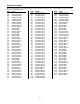
Program Field Index On the following pages, the programming fields have been arranged in numerical order. Use this index to cross-reference the fields on the programming form.
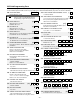
VISTA-40 Programming Form Some fields are programmed for each partition (shown as shaded fields). If you are programming a multiple-partition system, see the Partition-Specific Fields section for programming these fields. Standard default (*97) values are shown in brackets. | | | *00 INSTALLER CODE *25 BURG.TRIGGER FOR RESPONSE TYPE 8 Enter 4 digits, 0-9 [4140] *02 *05 [1] 1=enable; 0=disable RESPONSE TYPES FOR ZONES *26 INTELLIGENT TEST REPORTING Skip these fields.
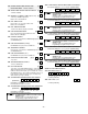
*39 ENABLE OPEN/CLOSE REPORT FOR *58 SUPERVISORY AND RESTORE CODES FOR ZONES [0] 01-16. Enter 00-09; B-F (11-15). Default = [00 00 00 00 00] INSTALLER CODE 1=enable; 0=disable *40 OPEN/CLOSE REPORT FOR KEYSWITCH [0] 1=enable; 0=disable *59 *41 NORMALLY CLOSED or EOLR (Zones 2-8) *62 [0] | | | Trbl Rst Byp Byp Rst ALARM REPORT CODES & ID DIGITS FOR ZONES 17-32. *63 SUPERVISORY AND RESTORE CODES FOR ZONES *42 DIAL TONE PAUSE 17-32. Enter 00-09; B-F (11-15).
*80 *81 SYSTEM NON-ALARM CODES Enter 00-09; B-F (11-15).
1*58 5800 RF BUTTON FORCE ARM 2*02 DAYLIGHT SAVING TIME [0] Enter "1" to enable. If a zone is faulted after pressing button, keypad will beep once. Pressing the button again within 4 sec. bypasses the zone. Enter "0" to disable. Must be "0" for UL installations.
Partition-Specific Fields (Duplicate this page for each partition in the installation.) To program these fields, 1. Press *91 to select a partition. 2. Enter a partition-specific field number (ex. *09). 3. Make the required entry. 4. Repeat steps 1-3 for the other partition in the system.
Programming With #93 Menu Mode NOTE: The following field should be preset before beginning: 2*00 Number of Partitions. In addition, receivers should be programmed via Device programming. After programming all system related programming fields in the usual way, press #93 while still in programming mode to display the first choice of the menu driven programming functions. Press 0 (NO) or 1 (YES) in response to the displayed menu selection. Pressing 0 will display the next choice in sequence.
Zone Programming If using 5800 Series transmitters, do not the install batteries until you are ready to enroll them. After enrolling the transmitter, the battery need not be removed. This is to prevent enrolling the wrong serial number. PROMPT EXPLANATION ZONE PROG? 1 = YES 0 = NO 0 Press 1 to enter ZONE PROGRAMMING mode. The following screens appear. Press [✱] to display the next screen. Press # to display a previous screen. SET TO CONFIRM? 1 = YES 0 = NO 0 ENTER ZONE NO.
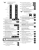
PROMPT EXPLANATION 10 INPUT TYPE RF Xmitter Enter the input device type as follows: 00 = not used 01 = hardwired 03 = supervised RF transmitter (RF type) 04 = unsupervised RF transmitter (UR type) 05 = RF button-type transmitter (BR type) 06 = serial number polling loop device (SL type) 07 = DIP switch-type polling loop device 08 = right loop of DIP switch type device Right loops refer to the use of the right loop on a 4190WH Zone Expander Module and/or 4278 PIR, which allow hardwired devices to be monit
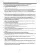
5800 Series Transmitters Loop Designations LOOP 3 LOOP 2 (REED) LOOP 1 (PRIMARY) LOOP 2 LOOP 2 (AUX.
PROMPT EXPLANATION ENTER ZONE NO. 00 = QUIT The system now returns to the “ENTER ZONE NO.” prompt for the next zone. When all zones have been programmed, enter 00 to quit. 11 After you have enrolled each wireless device, remove ONE of the serial number labels from that device and affix it in the appropriate column on the worksheets provided later in this Programming Guide; then enter the other information (zone number, zone type, etc.) relevant to that device.
PROMPT EXPLANATION 10 INPUT S/N: L A XXX-XXXX - If you entered RF, BR, UR or SL for the Input Type, this screen displays. Otherwise the summary screen for the next zone displays. Enter the 7-digit serial number, using one of the following methods: a. Transmit two open and close (or close and open) sequences. For a button-type transmitter, press and release the button, wait approximately 4 seconds, then press and release the button a second time. OR b.
PROMPT EXPLANATION Enter partition number for wireless key. Press [✱] to continue. PARTITION 1 The system searches for the highest available, consecutive 4-zone group (the four zones required for the 5804 and 5804BD), and displays the lowest zone number of the group. If you want to start at a different zone number, enter the zone desired and press [✱]. If that zone number is displayed, the system has the required number of consecutive zones available, beginning with the zone you entered.
Alpha Descriptors Programming You can program a user-friendly English language description/location for all protection zones, relays, keypad panics, polling loop short, and RF receiver supervision troubles. Each description can be composed of a combination of words (up to 3) that are selected from a vocabulary of 244 words stored in memory, and any word can have an "s" or " ’s " added to it. In addition, up to 20 installer-defined words can be added to those already in memory.
4. 5. 6. 7. Accept the word. To accept the word, press 6, which switches back to the alphabet list for the next word, or press 8 to store the complete descriptor and then exit. Select the next word. For selection of the next word (DOOR), repeat step 3a (word #057) or 3b, but selecting the word "DOOR.” To accept the word, press 6, which again switches back to alphabet list. Store the descriptor. When all desired words have been entered, press 8 to store the description in memory.
2. 3. 4. 5. 6. 7. Enter the custom word number (01-20) you want to create. For example, if you are creating the first word (or word string), enter 01; when creating the second word, enter 02, and so on. A cursor now appears at the beginning of the second line. Type the word using one of two methods as follows: a) Press [#], followed by the 2-digit entry for the first letter you would like to display (e.g., 65 for "A"). When the desired character appears, press 6 to select it.
Alpha Descriptor Vocabulary (For entering alpha descriptors. To select a word, press [#] followed by the word’s 3-digit number.) NOTE: This vocabulary is not to be used for relay voice descriptors. See the Relay Voice Descriptors section when programming relay voice descriptors.
Device Programming This menu is used to program keypads, receivers, and relay modules, etc. Device Address 00 is always set as an alpha keypad assigned to Partition 1 with no sounder suppression options, and these settings cannot be changed. From Data Field Programming mode, press [#]93 to display "ZONE PROG?" Press 0 repeatedly to display "DEVICE PROG?" PROMPT EXPLANATION DEVICE PROG? 1=YES 0=NO Press 1 to enter Device Programming.
Relay Programming The system supports up to 8 relay outputs. Relays can be used to perform many different functions and actions. Each relay must be programmed to begin one of three types of ACTIONS at a designated START event, and end that ACTION at a designated STOP event.
Relay Output Devices Programming From Data Field Programming Mode, press #93 to display the "ZONE PROG?" prompt. Press [0] (NO) to each menu option until the "RELAY PROG?" prompt appears. Press [1] (YES). While in this mode, press [✱] to advance to next screen. Press [#] to back up to the previous screen. PROMPT EXPLANATION ENTER RELAY # (00=QUIT) 01 Enter the relay (output device) identification number 01-08. This is a reference number only, used for identification purposes.
PROMPT EXPLANATION 02 START: PARTN ANY PARTITION If the starting event will be limited to occurring on a specific partition, enter the partition number (1-2) in which the start event will occur. Enter 0 for any partition. Press [✱] to continue. 0 Do not use a zone programmed with an RF Button (Input Type BR) to STOP a relay. The system will not deactivate the relay. PROMPT EXPLANATION 02 STOP: ZN LIST If a zone list is being used to stop this relay action, enter the zone list number, 1-4.
PROMPT EXPLANATION 01 ADD ZONE # 00=QUIT Using 2-digit entries, enter each zone to be included in this zone list. Press [✱] after you enter each zone number. When you have entered all zones, enter 00. Press [✱] to continue. 00 Enter 0 to save this zone list. Enter 1 to delete it. 01 Del Zn LIST ? 1=YES 0=NO 0 01 DEL ZONES ? 1=YES 0=NO 0 Enter 1 to delete one or more zones in that zone list. Enter 0 if no changes are necessary.
Relay Voice Descriptors and Custom Word Substitutes Vocabulary Word Index Air ............................ 116 Alarm ....................... 255 And .......................... 067 Apartment ................ 117 Appliances ............... 161 Area ......................... 118 Attic.......................... 119 Baby......................... 120 Back......................... 121 Bar ........................... 122 Basement................. 021 Bathroom ................. 051 Battery......................
System Layout Worksheets Before programming any security system, you should first define the installation. To help you lay out a partitioned system, use the following worksheets. This will further simplify the programming process. Descriptor (4-char max) PARTITIONS Sec. Sub. # Prim. Sub.
Addr 00. 01. 02. 03. 04. 05. 06. 07. 08. 09. 10. 11. 12. 13. 14. 15. Type DEVICES (keypads, 4204, rf receivers, vip module, lrr) Sound House Device Types: Part Opt ID 00 = Device Not Used 01 = Alpha Console 02 = Fixed-Word Console 03 = RF Receiver 04 = Relay Module 05 = Voice Module NOTES: Address 04 must be used for the Voice Module, if used.
– 29 – 25 24 23 22 21 20 19 18 17 16 15 14 13 12 11 10 9 8 7 6 5 4 3 2 1 Zone No. Zone Type Part 1-2 Input Type Serial # / Loop Rpt. Code ZONE DEFINITION FOR ZONES 01-25 Zone Information (part numbers) & Alpha Descriptor (3 words max.
– 30 – 50 49 48 47 46 45 44 43 42 41 40 39 38 37 36 35 34 33 32 31 30 29 28 27 26 Zone No. Zone Type Part 1-2 Input Type Serial # / Loop Rpt. Code ZONE DEFINITION FOR ZONES 26-50 Zone Information (part numbers) & Alpha Descriptor (3 words max.
– 31 – 64 63 62 61 60 59 58 57 56 55 54 53 52 51 Zone No. Zone Type Part 1-2 Input Type Serial # / Loop Rpt. Code ZONE DEFINITION FOR ZONES 51-64 Zone Information (part numbers) & Alpha Descriptor (3 words max.
ZONE DEFINITIONS FOR KEYPAD PANIC ZONES 95, 96, & 99 Enter yes/no for each partition (field *22) Zone No. Zone Type 1 2 Report Code Zone Information (part numbers) & Alpha Descriptor (3 words max.) 95 96 99 ZONE DEFINITIONS FOR SYSTEM ZONES; 70, 88; 89, 90, 91 & 97 Zone No. Zone Type Zone Information (part numbers) & Alpha Descriptor (3 words max.
Relay Outputs Worksheets Applicable only if relays (4204) or X-10 devices are used. Programmed in the #93 Menu Mode in the Relay Programming Section. Fill in the worksheet below and follow the procedure in the installation instructions as you enter the data during the displays and prompts that appear in sequence. Notes: 1. For 4204 the Device Programming section must be programmed for the device address. Set the DIP switches on the device for that address. 2.
ZONE LISTS FOR RELAY DEVICES – Programmed in the #93 Menu Mode in the Relay Programming Section. Fill in the required data on the worksheet below and follow the procedure shown earlier in this Programming Guide as you enter the data during the displays and prompts that appear in sequence. Up to 4 zone lists may be created Note: Record desired zone numbers below. More or fewer boxes than shown may be needed, as any list may include any or all of system's zone numbers.
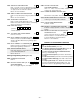
– 35 – RED (+) TRANSFORMER 16.5VAC, 40VA ADEMCO No.1361 (IN CANADA USE No. 1361CN) OR 1361X10 IF X-10 DEVICES WILL BE USED Connect to 24hr. 120VAC, 60 Hz Outlet - Blk Grn Yel - See Installation Instructions for maximum number of keypads and for maximum wire run length. SMOKE 2k EOLR (note 1,2) N.O. N.C. + ALL CIRCUITS ARE POWER LIMITED. AUXILARY POWER OUTPUT 9.6VDC - 13.
165 Eileen Way, Syosset, New York 11791 Copyright © 2004 Honeywell International, Inc. www.honeywell.