
Installation Instructions
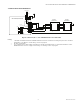
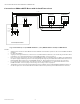
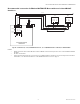
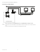
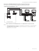
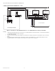
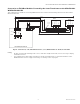
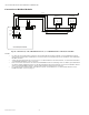
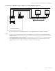
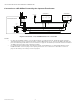
Table Of Contents

CPO-PC400-W/CPO-PC400-UW HVAC CONTROLLER
25 EN0B-0085 IE10 R0420
Connection to Field Bus Modules Powered by a Separate Transformer
This configuration has the advantage of allowing the FBAs to be distributed through a building.
CONNECTION VIA RS485 INTERFACES 1, 2, OR 3
Fig. 16. Connection (L > 3 m) of RS485 interfaces 1, 2, or 3 (RS485 interface 1 shown) to a Field Bus
NOTES:
— Signal ground (signal reference) connection is recommended. For more information, see “General Information
on the RS485 Standard” section on page 7.
— For communication cable lengths, transmission speeds, and termination, see “General Information on the
RS485 Standard” section on page 7.
TX
5V
GND
FBA #1
Isolaon
Barrier
RX
5V_ISO
GND_ISO
RS485+
RS485-
R
T
110VAC/230VAC
24VAC
FBA #N
F1
Field Bus +
Field Bus -
24VAC-COM
L > 3m
R
T
24VAC
Field Bus +
Field Bus -
24VAC-COM
24VAC
Shielding
Oponal
FGND
24V0
24V~
CH1+
CH1-
GND1
24VAC
F2
A
C
A+C = MAX.20 Meters
24VAC
F3
A
C
110VAC/230VAC 110VAC/230VAC
CPO-PC400-W/CPO-PC400-UW