
Install Instructions
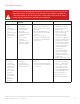
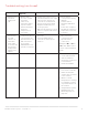

Problem Possible Cause or
Symptom
Test Procedure Solution
• HRV/ERV
operating
only on high
speed, no
communication
between unit &
wall controls.
• HRV/ERV
supply or
exhaust fan
runs only on
high.
• Dehumidistat of
the wall controls
activated.
• T3 Timer
20/40/60 mins.
activated.
• Short circuit
between G &
R terminals of
REMOTES on
Speed Control™.
• Faulty wire between
control and H/ERV.
• Faulty wall control.
• Disconnect all wall controls
from unit
• Ensure all other wall controls
are not in override mode.
• Inspect the wires to insure not
damage.
• Remove wall control and verify
it at the H/ERV.
• Ensure all wall controls
and Speed Control
wire connections
correspond to their
matching letters
• Ensure no nails, staples
or screws are shorting
out the wires.
• Replace LVC PCB
board, wall control and
wires.
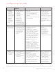
• Motor not
functioning.
• Motor failure.
• Failure to the HVC
or LVC PCB board.
• Wire connection or
wire sequence not
corresponding to
wiring diagram.
• Run capacitor
failure
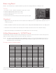
• Resistance test: Unplug
H/ERV unit and with a
multimeter
– Test the motor resistance
(BLUE & BLACK wires) of the
motor. The range should be
between 3339 Ohms
– Then proceed to measure the
resistance (BLUE & BROWN
wires) the range should be
between 5664 Omhs
• If resistance falls within the
above ranges the motor is
good.
• If capacitor is swollen or
disfigured, it is definitely bad.
• Check amperage in leads
going to capacitor when in
operation. If capacitor is open,
no amperage will flow.
• Remove from circuit and check
for short circuits or grounds
(use ohmmeter only).
• Replace the HVC or LVC
Board
• Correct faulty
connection or
wire sequence to
correspond to the
wiring diagram.
• Replace the run
capacitor and/or Motor
• Yellow
blinking LED
on speed
controller.
• Defrost Thermister
not properly
connected to HVC
Controller
• Defrost Thermister
is defective
• Ensure proper connection of
thermister.
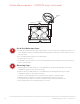
• Remove access panel to
expose HVC controller
verify defrost thermister is
connected to the “T2” terminal
on HVC controller.
• Unplug defrost thermister
from HVC controller & check
readings with Ohm meter.
• If defrost thermister
is not connected,
please plug-in on
HVC controller on
the terminals marked
“TEMP SENSOR”.
• Connect the Ohm
meter to red terminal
and if receive no
readings 0, replace
defrost thermister.
ERV/HRV Ventilation Systems 69-2480EF—19
36
Troubleshooting (continued)