
Install Instructions

Wiring (continued)
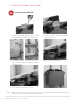
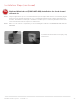
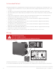
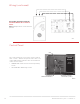
Control Panel
The control panel has a 3-position selector switch
and “+” and “–” buttons for speed control. The color
of the LED indicator indicates the current function
of the selector switch.
• GREEN LED = Mode Control (normal operating
mode)
• YELLOW LED = Balancing Control
ERV/HRV Ventilation Systems 69-2480EF—19
28
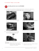
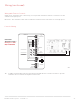
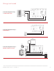
Follow this diagram if using the
20/40/60 Minute Boost Control
Timer.
Note: Multiple timers can be wired in
parallel.
M28996
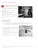
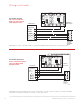
BGR
LED
3-POSITION
SELECT
OR SWITCH
SPEED CONTROL
BUTTONS (+ AND -)
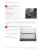
Speed
Control
Open for
Instructions
M32371