
Install Instructions
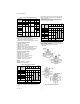
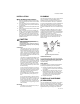
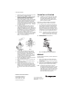
Table Of Contents

VCZA,B,M,N SERIES
Automation and Control Solutions
Honeywell International Inc.
1985 Douglas Drive North
Golden Valley, MN 55422
customer.honeywell.com
® U.S. Registered Trademark
© 2011 Honeywell International Inc.
95C-10948—02 T.D. Rev. 02-11
Printed in U.S.A.
1. Disconnect power supply before servicing to avoid
electrical shock or equipment damage.
2. Depending on the installation, it may be necessary
to disconnect leadwires to valve actuator, or
depress tab on Molex™ connector and remove.
Where appropriate, label wires for rewiring.
3. Remove valve actuator by pressing up on the latch
mechanism located directly below the red manual
open lever with thumb (See Figure 5). Simulta-
neously press the actuator down towards the valve
body with moderate hand force and turn the actua-
tor counter-clockwise by 1/8 turn (45°). Lift actua-
tor off the valve body.
4. To replace a cartridge, isolate flow to the valve
using installed shut off valves or other service
equipment designed for this purpose. Remove old
cartridge with 40007029-002 wrench supplied with
the replacement unit. It may be necessary to use
pliers or other tools to remove the old cartridge due
to calcium or dirt buildup in the valve body.
5. Clean the valve surfaces marked * and ** in Figure
6 to ensure the new cartridge O-rings seal at these
points. Use care to avoid damage to these sur-
faces (** for 3-way valves only).
6. Remove the pre-lubricated cartridge assembly
from its plastic bag. Thread it by hand into the
valve body and tighten it down with the enclosed
wrench until it bottoms out. DO NOT OVER
TIGHTEN: maximum torque is 40 in-lb. (4.5 Nm).
The top surface of the cartridge should be flush
with the top edge of the body casting.
7. Replace valve actuator by following the procedure
in the "To Install Actuator" section.
8. Reconnect leadwires or Molex™ connector if nec-
essary.
9. Refill hydronic system or restore system flow by
opening isolating valves.
10. Restore power, and checkout operation of car-
tridge in valve, making sure of no internal seat
leakage or external body leakage.Restore system
pressure slowly to the valve to allow any trapped
air to escape. Check for leaks. Re-install the actua-
tor.
TO INSTALL ACTUATOR
NOTE: Installation of a new actuator does not require
draining the system, provided the valve body
and valve cartridge assembly remain in the
pipeline. Wiring may be done either before or
after the actuator is installed.
Refer to the VC Actuator Installation and Instruction
sheet for detailed wiring and check-out instructions.
1. The actuator head is automatically latched to the
valve. Align the coupling hole in the bottom of the
actuator with the valve stem. Press the actuator
down towards the body with moderate hand force
and turn the actuator counter-clockwise by 1/8 turn
(45 degrees) to line up the actuator with the piping.
The lock will click when engaged (See Figure 7).
NOTE: The actuator can also be installed at right
angles to the valve body but in this posi-
tion the lock mechanism will not engage.
2. Connect leadwires.
3. Restore power and check operations.
Fig. 7. Lock Mechanism to detach Actuator
SERVICE
This valve should be serviced by a trained, experienced
service technician.
1. If the valve is leaking, drain system OR isolate
valve from the system. Do not remove valve body
from plumbing.
2. Check to see if the cartridge needs to be replaced.
3. If the motor or other internal parts of the actuator is
damaged, replace the entire actuator assembly.
NOTE: Honeywell VC series hydronic valves are
designed and tested for silent operation in prop-
erly designed and installed systems. However,
water noises may occur as a result of excessive
water velocity. Piping noises may also occur in
high temperature (over 212 °F [100 °C]) sys-
tems with insufficient water pressure.
Fig. 5. Installing
Cartridge
Fig. 6.
2