
Install Instructions
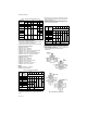
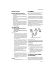
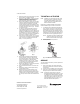
Table Of Contents

INSTALLATION INSTRUCTIONS
Place Bar Code Here
95C-10948-02
VCZA,B,M,N Series
CARTRIDGE VALVE FOR USE WITH VC SERIES
The VC hydronic valve consists of a valve body and
replaceable characterized cartridge assembly.
Depending on the valve model selected, they can be
used with a VC2114 or VC8114 series actuator to provide
on-off flow control, or with a VC6930 or VC7930 series
actuator to provide proportional flow control. Two way
bodies may be plumbed in either direction. Three-way
bodies may be used in either diverting or mixing
applications.
Replacing the cartridge rebuilds the valve. The valve
body should be able to stay in the pipes indefinitely.
VC actuators, ordered separately, use cam-operated
cartridge travel to resist water hammer. Limit switches
prevent motor overrun.
SPECIFICATIONS
The specifications following are nominal and conform to
generally accepted industry standards. Honeywell is not
responsible for damages resulting from misapplication or
misuse of its products or non-workmanlike installation
practices.
Operating Ambient:
32 to 150 °F (0 to +65 °C).
5-95% RH (non-condensing)
Fluid temperatures: 34 to 203 °F (1 to 95 °C)
Shipping and Storage Temperature: -40 to 150 °F
(-40 to +65 °C)
Atmosphere: Non-corrosive, non-explosive.
Valve Materials:
Body of bronze Cartridge of Ryton™ (polyphenylene sul-
phide)
and Noryl™ (polyphenylene oxide)
O-ring seals of EPDM rubber
Stem of stainless steel
Pressure Rating:
Static – 300 psig (20 Bar) maximum.
Burst – 1500 psig (100 Bar)
Operating Differential and Close-off – 60 psi maximum
(4 bar)
Stem Travel: 0.4 inches (10 mm)
Flow Characteristics: Linear or equal percentage, per
Table 2.
Spring Force:
1000 and 6000 Series (Silver): 14 lbf.
3000 and 7000 Series (Red): 20 lbf.
Fig. 1. Nominal dimensions in inches [millimeters]