
Install Instructions
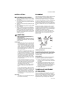
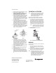
Table Of Contents

VCZA,B,M,N SERIES
3 95C-10948—02
INSTALLATION
When Installing This Product...
1. Read these instructions carefully. Failure to follow
them could damage the product or cause a hazard-
ous condition.
2. Check the ratings given in the instructions and on
the product to make sure the product is suitable for
your application.
3. Installer must be a trained and experienced service
technician.
4. Always conduct a thorough check-out when installa-
tion is completed.
5. While not necessary to remove the actuator from
the body, it can be removed for ease of installation.
The actuator can be installed in any of the four ori-
entations to suit the most convenient wiring direc-
tion. Actuator latching mechanism works only when
the lengths of the actuator and the valve body are
parallel to each other.
CAUTION
Disconnect power supply before connecting
wiring to prevent electrical shock and
equipment damage.
On 24V systems, never jumper the valve coil
terminals, even temporarily. This may damage
the thermostat.
PROPER USE
These valves are only for use in cold, warm, and
hot water applications. They are designed for a
medium temperature range of from 34 to 203 °F
(1 to 95 °C), at a maximum pressure of 300 psig
(20 bar). They are to be operated with the appro-
priate Honeywell actuators only. Water must be
properly filtered, treated and conditioned accord-
ing to local conditions.
The presence of suspended particulate(s) in the
system, such as detached calcium scale, sand,
silt, large quantities of magnetite, etc., can affect
operation of the valve. For trouble-free operation
of this product, good installation practice should
include initial system flushing, chemical water
treatment, and the use of a 50 micron (or finer),
10% system side-stream filter(s). Remove all fil-
ters before flushing.
Put the VC actuator manual lever in the fully up
position or the half open (down) position to allow
initial system flushing with the actuator mounted.
This may be done without electrical hook-up.
Alternatively, reusable flush caps,
part # 272866B, may be purchased separately
for use in initial flushing of dirty hydronic sys-
tems.
Do not use boiler additives, solder flux and wet-
ted materials which are petroleum based or con-
tain mineral oil, hydrocarbons, or ethylene glycol
acetate. Compounds which can be used, with
minimum 50% water dilution, are diethylene gly-
col, ethylene glycol, and propylene glycol (anti-
freeze solutions).
IMPORTANT
The presence of iron oxide (red rust) in the sys-
tem voids the valve warranty.
PLUMBING
The valve may be plumbed in any angle, including vertical
piping, but preferably not with the actuator below
horizontal level of the body. Make sure there is enough
room around the actuator for servicing or replacement.
For use in diverting applications, the valve is installed with
the flow water entering through bottom port AB, and
diverting through end ports A or B. In mixing applications
the valve is installed with inlet to A or B and outlet through
AB.
Mount the valve directly in the tube or pipe. Do not grip
the actuator while making and tightening up plumbing
connections. Either hold valve body in your hand or attach
adjustable spanner (38 mm or 1-1/2") across hexagonal
or flat faces on the valve body (Figure 4).
If assembling valve train on a bench, take care not to
deform body with vice. Do not place the raised "H" logo
between the jaws of the vice. Excess jaw force can
deform the body.
Fig. 4. Plumbing of the VC Valve
COMPRESSION MODELS
For compression fitted models, tighten the compression
nuts enough to make a watertight seal. TAKE CARE NOT
TO OVER TIGHTEN. Maximum torque limit is 33 ft-lb for
the 22 mm compression fitting, and 48 ft-lb for the 28
compression fitting.
SWEAT MODELS
On sweat fitted valves, the cartridge is shipped loose to
avoid being damaged during the solder operation.
1. Remove valve actuator from body and solder the
connecting pipes in accordance with normal solder-
ing practices.
2. After soldering and valve has cooled, remove car-
tridge assembly from plastic bag, insert into the
valve body and tighten down with enclosed wrench
until it bottoms out. DO NOT OVER TIGHTEN
(maximum torque is 40 in-lb). See Figure 5.
3. Replace valve actuator.
TO REPLACE CARTRIDGE
(IF REQUIRED)
Two-way cartridges fit all two-way bodies. The Cv rating
of a valve can be changed by replacing the cartridge,
allowing for unique combinations. Three-way cartridges fit
all three-way bodies. Cartridges for proportional control
applications have high force springs color-coded red.
M29716