
Product Overview
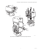
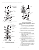
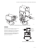
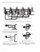
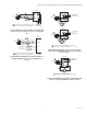
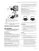
Table Of Contents

V4043A,B,E,J; V4044A,B; V8043A,B,E,F,J; V8044A,B,E MOTORIZED VALVES
17 60-2133—12
Fig. 26. Existing Dole System. (Wires are identified by
letters for easy correspondence to wires on Figs. 27 &
28.)
Fig. 27. Wiring a V8043E to a Dole System. (Wires are
identified with letters to correspond with wires on
Fig. 26.)
Fig. 28. Wiring a V8043F to a Dole system (2 options).
(Wires are identified with letters to correspond with
wires on Fig. 26.)
Fig. 29. Existing Flair System. (Wires are identified with
letters to correspond with wires on Figs. 30 & 31.)
L1
(HOT)
L2
1
A
B
F
D
E
THERMOSTAT
DOLE VALVE
TO TERMINALS
T, T ON
BURNER RELAY
1
POWER SUPPLY. PROVIDE DISCONNECT MEANS
AND OVERLOAD PROTECTION AS REQUIRED.
M5977
1
2
3
4
C
L1
(HOT)
L2
1
A
B
C
D
E
THERMOSTAT
V8043E
TO TERMINALS
T, T ON
BURNER RELAY
1
POWER SUPPLY. PROVIDE DISCONNECT MEANS
AND OVERLOAD PROTECTION AS REQUIRED.
M5965
YELLOW
YELLOW
RED
RED
F
A
B
C
F
THERMOSTAT
END SWITCH
V8043F
TH-TR
TH
TR
L1
(HOT)
L2
1
E
M5966
A
B
C
F
THERMOSTAT
END SWITCH
V8043F
TH-TR
TH
TR
L1
(HOT)
L2
1
E
TO TERMINALS
T, T ON
BURNER RELAY
TO TERMINALS
T, T ON
BURNER RELAY
D
D
POWER SUPPLY. PROVIDE DISCONNECT MEANS AND
OVERLOAD PROTECTION AS REQUIRED.
1
M5978
A
B
C
D
THERMOSTAT
FLAIR VALVE
L1
(HOT)
L2
1
F
TO TERMINALS
T, T O N
BURNER RELAY
POWER SUPPLY. PROVIDE DISCONNECT MEANS AND
OVERLOAD PROTECTION AS REQUIRED.
1
E
3
2
1
4
5