
Product Overview
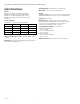
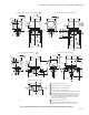
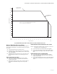
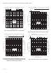
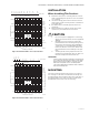
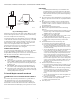
Table Of Contents

V4043A,B,E,J; V4044A,B; V8043A,B,E,F,J; V8044A,B,E MOTORIZED VALVES
60-2133—12 10
Fig. 9. Mounting positions.
Mount the valve directly in the tube or pipe. Make sure that
the flow through the valve is in the direction indicated by
the arrow stamped on the valve body.
On diverting valves, the three fittings or ports are labeled
on the bottom of the valve body casting. See Fig. 1. Port AB
is the inlet port and is open at all times. Port A is closed
when the valve is de-energized; port B is open when the
valve is de-energized. Refer to the equipment
manufacturer instructions to determine which port (A or
B) should be connected to the coil bypass.
FLARE FITTING MODELS
Use new, properly reamed pipe, free from chips. The valve
body is threaded for standard 5/8 in. OD copper, 45
degree SAE flare fitting nuts. These nuts are not furnished
with the valve and must be obtained separately.
SWEAT COPPER MODELS
1. Use new, properly reamed pipe, free from dents or
corrosion.
2. Place the valve on the pipe. Set the manual opening
lever to MAN. OPEN position before applying heat.
This protects the plug inside the valve by removing it
from the seat.
3. IMPORTANT- Take care not to burn the plastic por-
tion of the composite adapter plate when soldering.
4. Sweat the joints, keeping the outer surface free from
solder. DO NOT use silver solder because of the high
melting temperature required.
To Install Replacement Powerhead
SYSTEMS WITH OLD STYLE VALVE BODIES (SERIES 1-
5)
To install a replacement powerhead in a system with an
old style body (series 1-5), the valve body must be
converted to accept the new powerhead using part no.
40003918 Conversion Kit. The kit includes a metal plate
with a driveshaft and rubber plug, O-ring, and four screws.
IMPORTANT
Converting the valve body for use with the new
powerhead does not require removal of the valve
body from the pipeline. However, it is necessary to
drain the water from the system before beginning
the conversion.
1. Disconnect the power supply before connecting the
wiring to prevent electrical shock or equipment dam-
age.
2. Disconnect the leadwires to the powerhead at the
terminal block or conduit connection. Remove the
conduit or cable connector if fitted. Label each wire
for rewiring later.
3. Drain the water from the system.
4. Remove the old powerhead from the valve body
(Fig. 10)
a. Place the manual opening lever (normally closed
models only) on the old powerhead in the MAN.
OPEN position (see Fig. 10A).
b. Remove the cover (Fig. 10B).
c. With the cover off, remove the four screws secur-
ing the powerhead to the valve body.
d. Lift the powerhead off the valve body (Fig. 10C).
e. Remove the O-ring from the top of the valve
body.
5. Install 40003918 Conversion Kit (Fig. 11)
a. Insert the new O-ring in the valve body.
b. Place metal plate with the rubber plug on top of
the valve body. Make sure the guide pins on the
underside of the metal plate fit into the recesses
on the valve body.
c. Secure the metal plate to the valve body with the
four screws (two sets) provided. One set of
screws has heads with recessed threads to insert
screws for mounting the new powerhead; insert
this set into the larger screw openings. The other
set has domed heads; insert this set into the
smaller screw openings. Each set of screws must
be inserted in opposite corners of the metal plate
so the screws sit flat on the plate. Make sure the
guide pins on the plate fit into the recesses on
the valve body.
6. Install new powerhead (see Fig. 12)
a. Place the manual opening lever (normally closed
models only) on the new powerhead in the MAN.
OPEN position.
b. Fit the powerhead onto the valve body, ensuring
that the shaft seats correctly. The powerhead
should be aligned with the manual opening lever
or slot for lever at the port A end of the valve
body.
c. Secure the powerhead to the valve body with the
two screws provided.
d. If fitted, reconnect the conduit or cable. Recon-
nect the leadwires at the powerhead.
e. Replace the powerhead cover.
7. Turn on power.
M10162A
VERTICAL
PIPING
HORIZONTAL
PIPING