
Install Instructions
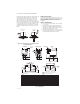
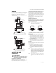
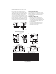
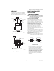
Table Of Contents

V4043, V4044, V8043 AND V8044 ZONE VALVES
95-6983EF—03 2
Mount the valve directly in the tube or pipe. Make sure
that the flow through the valve is in the direction
indicated by the arrow stamped on the valve body.
On diverting valves, the three fittings or ports are
labeled on the bottom of the valve body casting. See
Fig. 2. Port AB is the inlet port and is open at all times.
Port A is closed when the valve is de-energized; port B
is open when the valve is de-energized. Refer to the
equipment manufacturer’s instructions to determine
which port (A or B) should be connected to the coil
bypass.
Fig. 2. Inlet and outlet ports on straight-through
and diverting valves.
FLARE FITTING MODELS
Use new, properly reamed pipe, free from chips. The
valve body is threaded for standard 5/8 in. OD copper,
45 degree SAE flare fitting nuts. These nuts are not
furnished with the valve and must be obtained
separately.
SWEAT COPPER MODELS
1. Use new, properly reamed pipe, free from dents
or corrosion.
2. Place the valve onto the pipe. Set the manual
opening lever to MAN. OPEN position before
applying heat. This protects the plug inside the
valve by removing it from the seat.
3. Sweat the joints, keeping the outer surface free
from solder. DO NOT use silver solder because of
the high melting temperature required.
Fig. 3. Dimensions.
OUT
STRAIGHT THROUGH
VALVES
IN
B
A
M35994
OUT
OUT
B
A
AB
IN
2 POSITION
DIVERTING
VALVES
4-7/8 (124)
OUT
IN
1
END SWITCH
MAN
OPEN
AUTO
MAN
OPEN
AUTO
CLEARANCE
FOR COVER
REMOVAL
CONDUIT COVER
FOR V8043F
TERMINAL BOARDLEADWIRES
A
B
F
C
A
D
B
C
B
OUT
IN
N
M
R
S
L
K
H
J
G
SWEAT
3/8 FLARE
2
U
P
FNPT
CLEARANCE NECESSARY FOR COVER REMOVAL
FLAIR-TO-SWEAT UNION ADAPTER
1
2
M16851
DIMENSION IN INCHES (MM)
MODELS A B C D E F G H J
V8043C,D,G 2-3/8 (60) 3-3/4 (90) 7/8 (22) 3/4 (19) — 5-1/4 (133) 3-7/16 (87) 5/8 (16) —
V8043F 2-3/8 (60) 3-3/4 (90) 7/8 (22) 3/4 (19) 3-7/8 (98) 5-1/4 (133) 3-7/16 (87) — 3/4 (19)
SWEAT MODELS K L
5/8 IN. I.D. (FOR 1/2 IN. COPPER TUBING) 3-1/8 (79) 1-9/16 (40)
7/8 IN. I.D. (FOR 3/4 IN. COPPER TUBING) 3-1/2 (89) 1-3/4 (44)
1-1/8 IN. I.D. (FOR 1 IN. COPPER TUBING) 3-7/8 (98) 1-15/16 (49)
FLARE MODELS M N
3/8 IN NPT ONLY 4-5/8 (117) 2-5/8 (59)
FNPT MODELS P U
3/4 IN. 3-5/8 (98) 1-13/16 (46)
FLARE-TO-SWEAT UNION ADAPTER R S
FOR 1/2 IN. COPPER 6-3/16 (157) 3-29/32 (99)
FOR 3/4 IN. COPPER 6-7/16 (164) 4-13/16 (106)