
Install Instructions
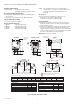
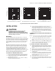
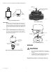
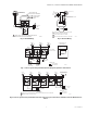
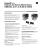
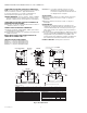
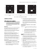
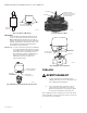
Table Of Contents

V8043C, D, F & G 5000 SERIES MOTORIZED ZONE VALVES
95C-10938EF—04 4
Fig. 3. Mounting Positions
IMPORTANT:
For normally closed models with sweat fittings, set
the opener lever to ‘MAN. OPEN’ before applying
heat to the fittings. This will protect the plug inside
the valve by removing it from the seat. After instal-
lation, place the manual opener in the ‘AUTO’ posi-
tion.
NOTE: New Buna-N rubber ball plug is impervious to
boiler or system additives. Petroleum base addi-
tives do not affect this ball plug. Steam applica-
tions require special ball plugs. Consult your local
Resideo representative.
Fig. 4. Removing Actuator from Valve Body.
Fig. 5. Shaft Position.
Fig. 6. Installing Actuator.
WIRING
CAUTION
1. Disconnect power supply before connecting
wiring to prevent electrical shock or equipment
damage.
2. On 24V systems, never jumper the valve coil
terminals even temporarily. This can burn out
the heat anticipator in the thermostat.
All wiring must conform to local electrical codes and
ordinances. Refer to Fig. 7 to 10 for wiring connections.
M10162A
VERTICAL
PIPING
HORIZONTAL
PIPING
3. LIFT ACTUATOR
STRAIGHT UP
2. DEPRESS
LOCKING
BUTTON
AUTO
1. PLCE MANUAL
LEVEL IN OPEN
POSITION
OPEN
M16858
PARALLEL FLAT SURFACES
ALIGN WITH NOTCH ON SIDE
OF VALVE BODY
DOUBLE-D
SHAFT
NOTCH
M16857
ACTUATOR
COUPLING
NOTCH
NOTCH TAB
M16859