
Install Instructions
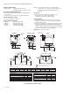
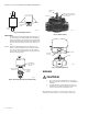
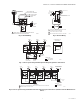
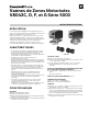
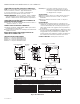
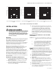
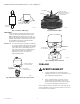
Table Of Contents

V8043C, D, F & G 5000 SERIES MOTORIZED ZONE VALVES
3 95C-10938EF—04
Fig. 2. Flow Characteristic Charts for V8043.
INSTALLATION
CAUTION
Normally it is not necessary to remove the
powerhead from the valve body during
installation. If the valve must be disassembled
with the water flow arrow pointing away from the
manual opening or lever slot.
Mounting
The valve may be mounted in any position on a vertical
line with the electrical connections on top. On a horizontal
line, the valve must be mounted so that the powerhead is
even with or above the center line of the piping as shown
in Fig. 3. Make sure that enough room is provided above
the powerhead to remove the cover for servicing. See
Fig. 1.
Mount the valve directly in the pipe or tube. It must be
installed so that the arrow stamped on the valve body’s
side corresponds to the flow direction. For flare-fitting
models, the body is threaded for standard 3/8 in. I.D.
copper, 45 degree SAE flare-fitting nuts. These nuts are
not furnished with the valve and must be obtained
separately. For sweat copper fittings, make sure that good
solder connections are made. DO NOT use silver solder
because of the high melting temperature it requires.
TO INSTALL A COMPLETE VALVE (V8043)
1. Disconnect power supply before connecting wiring
to prevent electrical shock or equipment damage.
2. Install valve into pipe on the return side of the coil.
(See Mounting Section.)
3. Make wiring connections to valve. (Refer to Wiring
section for proper instructions.)
4. Inspect the valve installation to ensure that all con-
nections and adjustments have been correctly
made. Adjust the thermostat or controller connected
to the valve so that the valve runs through its cycle.
Make sure the valve runs smoothly and positively
from closed to open to closed again. (See Operation
and Checkout Sections.)
TO REMOVE THE ACTUATOR FROM THE VALVE BODY
(SEE FIG. 3)
NOTE: It is not necessary to drain the hydronic system if
the valve body assembly remains in the pipe line.
1. Switch power supply OFF. Disconnect electrical
leads carefully, noting the position and color of each
lead.
2. Place the manual lever on the MAN. OPEN position.
3. Remove actuator by fully depressing spring release
button and lift it straight off of the body.
TO INSTALL ACTUATOR ON THE VALVE BODY
1. Align the parallel flat surfaces in double-D shaft of
valve body with notch in side of body (i.e. 90° to water
flow.) See Fig. 4. This makes actuator attachment
easier.
2. Wiring connections may be made either before or
after actuator installed on valve body.
3. Place the manual lever on the actuator in the MAN.
OPEN position.
4. Line up motor coupling to the parallel flat surfaces
in double-D shaft of body and fit the actuator onto
the valve body, ensuring that the shaft seats cor-
rectly. (See Fig. 5).
5. Snap actuator onto body by pressing down.
6. The manual lever may be released manually, but it is
also automatically released when the valve is oper-
ated electrically.
-50 (149)
-40 (119)
-30 (89.5)
-20 (60)
50.0 (345)
10.0 (69)
5.0 (34)
1.0 (7)
0.50 (3.4)
0.10 (0.69)
0.05 (0.34)
0
0
2
(0.13)
4
(0.25)
6
(0.38)
8
(0.5)
10
(0.63)
12
(0.76)
14
(0.88)
-0.05 (0.15)
-0.1 (0.3)
-0.5 (1.5)
-1 (3)
-5 (15)
-10 (30)
M5979B
GAL/MIN (l/s) FLOW RATE
PRESSURE DROP FT OF WATER psi (kPa)
PRESSURE DROP psi (kPa)
3.5CV
(3.0 KV)
-50 (149)
-40 (119)
-30 (89.5)
-20 (60)
50.0 (345)
10.0 (69)
5.0 (34)
1.0 (7)
0.50 (3.4)
0.10 (0.69)
0.05 (0.34)
0.01
0
2
(0.13)
4
(0.25)
6
(0.38)
8
(0.5)
10
(0.63)
12
(0.76)
14
(0.88)
16
(1.0)
18
(1.1)
20
(1.3)
22
(1.4)
24
(1.5)
26
(1.6)
28
(1.8)
30
(1.9)
-0.05 (0.15)
-0.1 (0.3)
-0.5 (1.5)
-1 (3)
-5 (15)
-10 (30)
M9186A
GAL/MIN (l/s) FLOW RATE
FT OF WATER psi (kPa) PRESSURE DROP
PRESSURE DROP psi (kPa)
8CV
(6.9 KV)
-50 (149)
-40 (119)
-30 (89.5)
-20 (60)
30 (207)
20 (138)
10 (69)
9 (62)
8 (55)
7 (48)
6 (41)
5 (34)
4 (28)
3 (21)
2 (14)
1 (7)
0
2
(0.13)
4
(0.25)
6
(0.38)
8
(0.5)
10
(0.63)
12
(0.76)
-5 (15)
-10 (30)
M9183A
GAL/MIN (l/s) FLOW RATE
FT OF WATER psi (kPa) PRESSURE DROP
PRESSURE DROP psi (kPa)
1CV
(0.86 KV)
Fig. 2a. Flow characteristics of 1 Cv (0.86 kV) flow.
Fig. 2b. Flow characteristics of 3.5 Cv (3.0 kV) valve. Fig. 2c. Flow characteristics of 8 Cv (6.9 kV) valve.