
Install Instructions
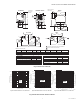
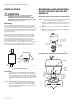
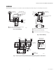
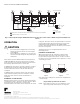

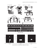
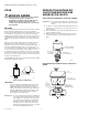
Table Of Contents

V8043C,D,F & G MOTORIZED ZONE VALVES
© 2020 Resideo Technologies, Inc. All rights reserved.
The Honeywell Home trademark is used under license from Honeywell International, Inc. This product is manufactured by Resideo Technologies, Inc. and its affiliates.
Tous droits réservés. La marque de commerce Honeywell Home est utilisée avec l’autorisation d’Honeywell International, Inc. Ce produit est fabriqué par Resideo Technologies, Inc. et ses sociétés affiliées.
www.resideo.com
Resideo Technologies, Inc.
1985 Douglas Drive North, Golden Valley, MN 55422
1-800-468-1502
95C-10926EF—04 M.S. Rev. 04-20 | Printed in United States
Fig. 7. 5-Zone System using an AT72A transformer to power up to 4-zone valves. (AT20B can power maximum of 2
valves).
OPERATION
CAUTION
1. Disconnect power supply before connecting
wiring to prevent electrical shock and equip-
ment damage.
2. Never jumper the supply wires or actuator ter-
minals even temporarily. This may damage the
thermostat.
The actuator has three different manual settings: AUTO,
OPEN and SWITCH (on 300 psi models only). In AUTO
mode, the valve cycles with the thermostat and activates
the auxiliary switch when valve is at full open.
In OPEN mode, the valve is opened to allow the system to
be filled, flushed or drained. The auxiliary switch is not
activated. The valve returns to AUTO mode when it is
energized.
In SWITCH mode (on 300 psi models only), the valve is
opened and the auxiliary switch is activated to run the
pump. The valve returns to AUTO mode when it is
energized.
NORMALLY CLOSED MODELS
With the manual opener set to AUTO and the powerhead
energized, the valve is opened as shown in Fig. 8-1. When
the powerhead is de-energized, a spring return
mechanism drives the valve to the closed positions shown
in Fig. 8-2. The valve can also be opened with no electrical
power by moving the manual opener lever over the stop
and pushing slowly and firmly to the ‘MAN. OPEN’*
position. The valve will return to automatic position when
the valve is energized.
*Auxiliary switch is not energized when the valve is
manually opened.
NORMALLY OPEN MODELS
When the powerhead is de-energized, a spring return
mechanism drives the valve to the open position. See
Fig. 8-1. When energized, the valve is closed as shown in
Fig. 8-2. A reverse acting thermostat is required to control
a normally open valve.
Note: Inlet port is stamped ‘A’, outlet Port is stamped ‘B’ on
the valve body.
Fig. 8. V8043 Operation for N.C. Valve.
NOTE: These hydronic valves are not suitable for use in
open loop systems where there is air exposure.
ZONE 1
T87
ZONE 2
T87
ZONE 3
T87
ZONE 4
T87
ZONE 5
T87
V8043F
END SWITCH
TH-TR
TH
TR
V8043F
END SWITCH
TH-TR
TH
TR
V8043F
END SWITCH
TH-TR
TH
TR
V8043F
END SWITCH
TH-TR
TH
TR
V8043F
END SWITCH
TH-TR
TH
TR
TO 120V
LINE
1
1
POWER SUPPLY. PROVIDE DISCONNECT MEANS AND OVERLOAD PROTECTION AS REQUIRED.
MAXIMUM CURRENT: 4.40 AMP. AT 120VAC
24V
TRANSFORMER
L1
(HOT)
L2
TO 120V
LINE
1
AT20B
TRANSFORMER
L1
(HOT)
L2
TO BURNER AND/OR
CIRCULATOR CIRCUIT
2
2
M16856
LOW VOLTAGE
LINE VOLTAGE
WIRING CODE
B
OUT
OPEN POSITION
A
IN
B
OUT
CLOSED POSITION
A
IN
M16955
Fig. 8-1.
Fig. 8-2.