
Install Instructions
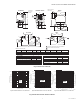
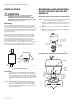
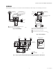
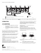

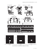
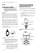
Table Of Contents

V8043C,D,F & G MOTORIZED ZONE VALVES
95C-10926EF—04 4
INSTALLATION
CAUTION
Normally it is not necessary to remove the
powerhead from the valve body during
installation. The valve must be disassembled
with the water flow arrow pointing away from the
manual opening or lever slot.
Mounting
The valve may be mounted in any position on a vertical
line. On a horizontal line, the valve must be mounted so
that the powerhead is even with or above the center line of
the piping as shown in Fig. 3. Make sure that enough room
is provided above the powerhead to remove the cover for
servicing. See Fig. 1.
Mount the valve directly in the pipe or tube. It must be
installed so that the arrow stamped on the valve body’s
side corresponds to the flow direction. For flare-fitting
models, the body is threaded for standard 3/8 in. I.D.
copper, 45 degree SAE flare-fitting nuts. These nuts are
not furnished with the valve and must be obtained
separately. For sweat copper fittings, make sure that good
solder connections are made. DO NOT use silver solder
because of the high melting temperature it requires.
Fig. 3. Mounting Positions
IMPORTANT:
For normally closed models with sweat fittings, set
the opener lever to ‘MAN. OPEN’ before applying
heat to the fittings. This will protect the plug inside
the valve by removing it from the seat. After instal-
lation, place the manual opener in the ‘AUTO’ posi-
tion.
NOTE: New Buna-N rubber ball plug is impervious to
boiler or system additives. Petroleum base addi-
tives do not affect this ball plug. Steam applica-
tions require special ball plugs. Consult your local
Resideo representative.
REMOVING AND MOUNTING
OF ACTUATOR FOR 300 PSI
MODELS
REMOVING THE ACTUATOR FROM THE VALVE BODY
NOTE: It is not necessary to drain the system if the valve
body assemby remains in the pipeline.
1. Turn power supply OFF. Disconnect electrical leads
carefully, noting the position and colour of each
lead.
2. Place the manual operating lever in the OPEN posi-
tion.
3. Remove actuator by fully depressing locking button
and lifting straight up.
MOUNTING THE ACTUATOR ON THE VALVE BODY
M10162A
VERTICAL
PIPING
HORIZONTAL
PIPING
3. LIFT ACTUATOR
STRAIGHT UP
2. DEPRESS
LOCKING
BUTTON
AUTO
1. PLACE MANUAL
LEVEL IN OPEN
POSITION
OPEN
M16858
4. ACTUATOR
COUPLING
M32279
1. NOTCH
3. PLACE THE
MANUAL
OPERATING
LEVER IN
THE OPEN
POSITION
2. ENSURE SHAFT
SLOT POINTS
TOWARDS NOTCH
ON SIDE OF BODY
FOR FITTING INTO
THE ACTUATOR
COUPLING
5. LINE UP
ACTUATOR
COUPLING
TO SLOT IN
SHAFT AND
SNAP DOWN
TO LOCK