
Product Overview
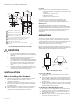
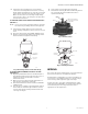
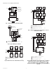
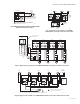
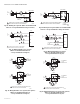
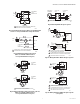
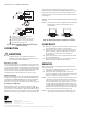
Table Of Contents

V8043A, E, F 5000 SERIES ZONE VALVES
3 95C-10932—04
4. Inspect the valve installation to ensure that all
connections and adjustments have been correctly
made. Adjust the thermostat or controller connected
to the valve so that the valve runs through its cycle.
Make sure the valve runs smoothly and positively
from closed to open to closed again. (See Operation
and Checkout Sections.)
TO REMOVE THE ACTUATOR FROM THE VALVE BODY
(SEE FIG. 3)
NOTE: It is not necessary to drain the hydronic system if
the valve body assembly remains in the pipe line.
1. Switch power supply OFF. Disconnect electrical
leads carefully, noting the position and color of each
lead.
2. Place the manual lever in the MAN. OPEN position.
3. Remove actuator by fully depressing spring release
button and lift it straight off of the body.
Fig. 3. Removing Actuator from Valve Body.
TO INSTALL REPLACEMENT ACTUATOR ON THE
VALVE BODY
1. Align the parallel flat surfaces in double-D shaft of
the valve body with notch in side of body (i.e. 90° to
water flow.) See Fig. 4. This makes actuator
attachment easier.
2. Wiring connections may be made either before or
after actuator installed on valve body.
3. Place the manual lever on the actuator in the MAN.
OPEN position.
4. Line up motor coupling to the parallel flat surfaces
in the double-D shaft of body and fit the actuator
onto the valve body, ensuring that the shaft seats
correctly. (See Fig. 5.)
5. Snap actuator onto body by pressing down.
6. The manual lever may be released manually, but it is
also automatically released when the valve is
operated electrically.
Fig. 4. Shaft Position.
Fig. 5. Installing Actuator.
WIRING
Disconnect the power supply before connecting wiring to
prevent electrical shock or equipment damage.
All wiring must comply with local codes and ordinances.
Connections to the individual valves are shown in Fig. 6
and 7. See Fig. 8 through 14 for typical hookups.
If replacing a Taco, Dole, Flair or White Rodgers 3-wire
valve with a 2-wire V8043E or F, see Fig. 15 through 27.
Check that the pressure rating of the new valve is
appropriate for the application.
2. DEPRESS
LOCKING
BUTTON
3. LIFT ACTUATOR
STRAIGHT UP
1. PLACE MANUAL
LEVER IN OPEN
POSITION
AUTO
M32207
OPEN
PARALLEL FLAT SURFACES
ALIGN WITH NOTCH ON SIDE
OF VALVE BODY
DOUBLE-D
SHAFT
NOTCH
M16857
ACTUATOR
COUPLING
NOTCH
NOTCH TAB
M16859