
Product Overview
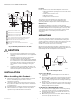
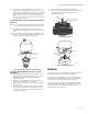
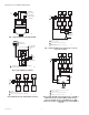
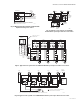
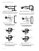
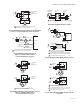
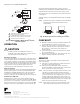
Table Of Contents

V8043A, E, F 5000 SERIES ZONE VALVES
95C-10932—04 2
Fig. 1. Mounting Dimensions in in. (mm).
CAUTION
1. Disconnect power supply before connecting
wiring to prevent electrical shock or equipment
damage.
2. Normally it is not necessary to remove the
actuator from the valve body during
installation. If the valve must be disassembled,
be certain that it is reassembled with the water
flow in the direction of the arrow. Reversal of
the actuator results in damage to the gear
train.
3. On 24 V systems, never jumper the valve coil
terminals even temporarily. This can burn out
the heat anticipator in the thermostat.
INSTALLATION
When Installing this Product...
1. Read these instructions carefully. Failure to follow
them could damage the product or cause a
hazardous condition.
2. Check the ratings given in the instructions and on
the product to make sure the product is suitable for
your application.
3. Installer must be a trained, experienced technician.
4. After installation is complete, check out product
operation as provided in these instructions.
Location
Install the valve in an area with adequate clearance to:
— Move the manual opening lever on the side of the
actuator.
— Remove the actuator cover.
— Wire the actuator.
— Replace the actuator motor.
The valve location should be in an area where the
temperature does not exceed the maximum valve
operating ambient temperature and fluid temperature.
Manual Lever
The V8043 normally closed valves can be opened
manually by moving the manual lever slowly and firmly to
the MAN. OPEN position and pushing up to the stop. The
stop permits the valve to be locked in the open position.
The valve returns to automatic position when it is
energized.
MOUNTING
The valve can be mounted in any position on a vertical
line. See Fig. 2. If the valve is mounted horizontally; the
actuator must be even with or above the center line of the
piping. Make sure to leave enough room above the
actuator to remove the cover for servicing.
Mount the valve directly in the tube or pipe after the coil.
Make sure that the flow through the valve is in the direction
indicated by the arrow stamped on the valve body.
Fig. 2. Mounting Positions.
Sweat Copper Models
1. Use new, properly reamed pipe, free from dents or
corrosion.
2. Place the valve on the pipe. Set the manual opening
lever to MAN. OPEN position before applying heat.
This protects the plug inside the valve by removing it
from the seat.
3. Sweat the joints, keeping the outer surface free from
solder. DO NOT use silver solder because of the high
melting temperature required.
TO INSTALL A COMPLETE VALVE (V8043):
1. Disconnect power supply before connecting wiring
to prevent electrical shock or equipment damage.
2. Install valve into pipe on the return side of the coil.
(See Mounting Section.)
3. Make wiring connections to valve. (Refer to Wiring
section for proper instructions.)
HEIGHT NEEDED TO REMOVE COVER.
DIMENSIONS FOR 1/2 IN. COPPER TUBING.
DIMENSIONS FOR 3/4 IN COPPER TUBING.
DIMENSIONS FOR 1 IN. COPPER TUBING.
4-7/8 IN. (124) MAX ON V8034F WITH TERMINAL BOARD ENCLOSURE.
V4034B AND V8043B VALVES THAT ARE NORMALLY OPEN IN THE
DE-ENERGIZED POSITION HAVE NO MANUAL LEVER.
REFER TO MOUNTING INSTRUCTIONS.
OPENING FOR 1/2 IN. CONDUIT ON MANUAL LEVER SIDE FOR
V4043, V8043.
1
2
3
4
5
6
7
8
AUTO
MAN OPEN
AB
8
1
6
5
2
3
4
V043, V8043 SWEAT COPPER CONNECTION MODELS
2-3/8
(60)
7/8 DIA.
(22)
1-1/2
(38)
5-1/4
(133)
15/32
(12)
IN
OUT
3-1/2 (89)
1-3/4
(44)
3/8
(10)
1-3/4
(44)
1-9/16
(40)
1-3/4
(44)
3-1/8
(79)
3-1/2
(89)
1-7/8
(47)
3-11/16
(94)
M32223
M10162
A
VERTICAL
PIPING
HORIZONTAL
PIPING