
Instructions / Assembly
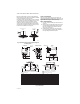
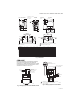
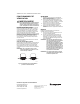
Table Of Contents

V4043, V4044 VALVES; V8043, V8044 ZONE VALVES
3 95-6983EF—01
WIRING
Disconnect the power supply before connecting wiring to
prevent electrical shock or equipment damage.
All wiring must comply with local codes and ordinances.
Connections to the individual valves are shown in Fig. 4-5.
Fig. 4. Typical wiring for V8043E, V8044E.
Fig. 5. Typical wiring for V8043F.
OPERATION AND CHECKOUT
CAUTION
On 24 V systems, never jumper the valve coil
terminals even temporarily. This may burn out
the heat anticipator in the thermostat.
NORMALLY CLOSED MODELS
With the manual opener set to AUTO and the powerhead
energized, the valve is opened as shown in Fig. 6A. When
the powerhead is de-energized, a spring-return
mechanism drives the valve to the closed position as
shown in Fig. 6B. The valve can also be opened with no
electrical power by moving the manual opening lever over
the stop and pushing slowly and firmly to the MAN. OPEN
position. The stop permits the valve to be locked in the
open position. The valve will return to the automatic
position when the valve is energized.
Auxiliary switch is not energized when the valve is
manually opened.
NORMALLY OPEN MODELS
When the powerhead is de-energized, a spring-return
mechanism drives the valve to the open position (Fig. 6A).
When energized, the valve is closed as shown in Fig. 6B.
A reverse-acting thermostat is required to control a
normally open valve.
NOTE: Inlet Port is stamped “A”, Outlet Port is
stamped “B” on the valve body.
Fig. 6. V8043 operation for normally closed valve.
Checkout
1. Raise the setpoint on the zone thermostat above
the room temperature to initiate a call for heat.
2.
Observe all control devices—the valve should open
and the auxiliary switch should make the circuit to
the circulator or other valve at the end of the open-
ing stroke.
3. Lower the setpoint on the zone thermostat below
the room temperature.
4. Observe the control devices. The valve should
close and the auxiliary equipment should stop.
Service
This valve should be serviced by a trained, experienced
service technician.
1. If the valve is leaking, drain the system and check to
see if the O-ring needs replacing.
2. If the gear train is damaged, replace the entire pow-
erhead assembly. See the Installation section. If the
motor is burned out, replace the motor. See
Replacement Parts list in the TRADELINE® Cata-
log.
NOTE: Honeywell zone valves are designed and
tested for silent operation in properly
designed and installed systems. However,
water noises may occur as a result of exces-
sive water velocity or piping noises may
occur in high temperature (over 212° F
[100° C]) systems with insufficient water
pressure.
NOTE: These hydronic valves are not suitable for
use in open loop systems where there is air
exposure.
AUXILIARY
SWITCH
MOTOR
YELLOW
LEADS
TO CIRCULATOR
OR ANOTHER VALVE
RED LEADS
THERMOSTAT
(TYPICALLY T87F)
TO
LINE
M5953
R
L1
(HOT)
L2
1
1
POWER SUPPLY. PROVIDE DISCONNECT MEANS AND
OVERLOAD PROTECTION AS REQUIRED.
END SWITCH
TO CIRCULATOR
OR ANOTHER
VALVE
TH
TR
24V
TRANSFORMER
THERMOSTAT
(TYPICALLY T87F)
TH TR
M5952
B
OUT
OPEN POSITION
A
A
IN
B
OUT
CLOSED POSITION
B
A
IN
M5951