
Product Overview
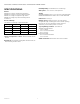
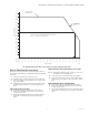
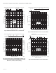
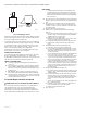
Table Of Contents

V4043A,B,E,J; V4044A,B; V8043A,B,E,F,J; V8044A,B,E MOTORIZED VALVES
7 60-2133—12
Fig. 2. Maximum temperature characteristics of valves with Class F motors.
How to Find Valve Pressure Drop
The pressure drop in psi (kPa), equivalent ft (m) of pipe, or
feet of water (kPa) may be calculated from Fig. 3 through 8
as follows:
1. Calculate the flow rate to heat the zone.
2. Determine the Cv (kV) rating of the motorized valve.
3. Select the graph corresponding to the Cv (kV) rating
(Fig. 3 through 8).
4. Determine the pressure drop across the valve using
the following procedures for calculating pressure
drop.
PRESSURE DROP IN PSI (KPA)
1. Locate the flow rate at the bottom of the graph.
2. Draw a line upward from the flow rate to the inter-
section of the curve.
3. Draw a line from the intersection to the left edge of
the graph to determine the pressure drop in psi
(kPa).
PRESSURE DROP IN EQUIVALENT FT (M) OF PIPE
NOTE: Both 1/2 and 3/4 in. pipe conversion scales are
available for this determination.
1. Locate the flow rate at the bottom of the graph.
2. Draw a line vertically to the top of the graph. Deter-
mine the pressure drop for either the 1/2 or 3/4 in.
pipe.
PRESSURE DROP IN FT OF WATER (KPA)
1. Locate the flow rate at the bottom of the graph.
2. Draw a line upward from the flow rate to the inter-
section of the curve.
3. Draw a line from the intersection to the right edge of
the graph to determine pressure drop in ft of water
(kPa).
EXAMPLE: 150°F (66°C) IS THE AMBIENT TEMPERATURE AT THE VALVE,
235F (113C) IS MAXIMUM FLUID TEMPERATURE.
MAXIMUM AMBIENT
TEMPERATURE LINE
MAXIMUM FLUID
TEMPERATURE
LINE
AMBIENT TEMPERATURE
FLUID TEMPERATURE
M8164
210
(99)
200
(93)
190
(88)
180
(82)
170
(77)
160
(71)
150
(66)
140
(60)
130
(54)
120
(49)
110
(43)
100
(38)
90
(32)
80
(27)
DEGREES F
DEGREES C
70
(21)
80
(27)
90
(32)
100
(38)
110
(43)
120
(49)
130
(54)
140
(60)
150
(66)
160
(71)
170
(77)
180
(82)
190
(88)
200
(93)
210
(99)
220
(104)
230
(110)
240
(116)
250
(121)