
Install Instructions

V4043 MOTORISED ZONE VALVE
3 95C-10388—07
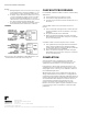
WIRING
Below are the wiring connections. Ensure the fixed wiring
connection to the mains supply is via a fuse rated at not
more than 3 amps and with a Class ‘A’ switch (having
contact separation of at least 3 mm in all poles).
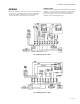
SUNDIAL PLANS
Start with valve(s), making sure each numbered or lettered
terminal - or coloured wire in case of valve - on unit being
connected, is wired correctly to numbered terminal at
junction box. Ensure all connections are good and all
terminal screws are firmly tightened.
Fig. 4. Wiring Diagram: S Plan.
Fig. 5. Wiring Diagram: C Plan.