
Install Instructions

V4043 MOTORISED ZONE VALVE
95C-10388—07 2
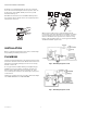
Normally-closed V4043 models incorporate a manual
lever; this should normally be in ‘AUTO’ position, but can
be moved to centre ‘MAN. OPEN’ position for system
draindown/filling, etc.
N.B. With the manual lever in the ‘MAN. OPEN’ position,
the auxiliary switch remains in the de-energized position
until power is restored.
INSTALLATION
Before commencing the fitting of the valve, read through
the plumbing and wiring instructions.
PLUMBING
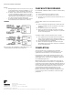
The valve may be plumbed in at any angle, but must not be
mounted so that the valve head is below horizontal level of
pipework. In the highly unlikely event of a leak, a safety
hazard could result.
Do not grip valve head while making and tightening up
plumbing connections. Either hold brass body in your
hand or attach adjustable spanner (32 mm or 1 1/4”)
across hexagonal or flat faces in valve body at each port’s
screw thread.
Tighten the compression nuts enough to make watertight
seal. TAKE CARE NOT TO OVER TIGHTEN.
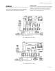
When used to form part of a central heating system,
positioning of the valve will depend on whether it is being
used on heating or hot water circuit. On either circuit, it
must not be fitted so that system vent, cold feed, or any
bypass is blocked when valve is closed. Typical SUNDIAL
SYSTEM CONTROL applications:
Fig. 2. Plumbing Diagram: C Plan.
Fig. 3. Plumbing Diagram: S Plan.
AUTO
MAN
OPEN
AUTO
MAN
OPEN
AUTO
MAN
OPEN
NO
M32224
NO