
User Guide
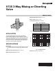
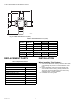
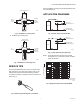
Table Of Contents

V135 3-WAY MIXING OR DIVERTING VALVE
95C-10711—01 2
Fig. 2. V135A dimensions in in. (mm.).
Table 2. V135 Dimensions in in. (mm).
REPLACEMENT PARTS
Table 3. Replacement Parts.
INSTALLATION
When Installing This Product…
1. Read these instructions carefully. Failure to follow them
could damage the product or cause hazardous condi-
tions.
2. Before installation, make sure that the inside of the
valve is clean and free of any packing materials, etc.
The supply line should be flushed out to clear of any
sediment, scale, or foreign material.
3. Installation as a mixing valve:
h
H
max.
L
SIZE
SIZE
SIZE
M28693
Item
Number Size (in.)
LH max. h
Sweat Union
V135A1006 3/4 5-1/8 (128) 3-1/4 (83) 2-9/16 (64)
V135A1014 1 5-13/16 (148) 3-1/4 (83) 2-15/16 (74)
V135A1063 1-1/4 6-3/8 (162) 3-1/4 (83) 3-3/8 (86)
NPT Threaded Union
V135A1022 1-1/4 7-1/8 (180) 3-1/4 (83) 3-3/4 (95)
V135A1048 1-1/2 8-5/16 (211) 3-11/16 (94) 4-3/16 (106)
Description Part Number
Cartridges
3/4 in. valve V135A-12VE
1 in. and 1-1/4 in. valves V135A-1VE
1-1/2 in. valve V135A-11/2VE
Gaskets (packages of 10)
1/2 and 3/4 in. valves 0901444
1 in. valve 0901445
1-1/4 in. valve 0901446
1-1/2 in. valve 0901447
Plastic handle for manual shutoff H100-1/2A