
Install Instructions
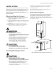
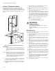
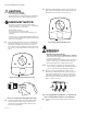
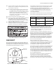
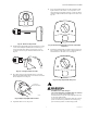
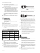
Table Of Contents

UV100E ULTRAVIOLET SYSTEMS
7 68-0262—09
16. For air treatment systems, wait ten minutes for the
airflow sensor to calibrate. During this time, the fur-
nace fan must remain off.
NOTE: Failure to wait ten minutes for the airflow sensor
to calibrate before powering the furnace causes
the airflow sensor to incorrectly calibrate and the
device to incorrectly function. If this occurs,
remove power to the furnace or turn off the sys-
tem and fan, wait ten minutes, and then resume
normal furnace operation.
17. Reconnect the power to the HVAC system.
18. Choose a location on the adjacent HVAC equipment
for the HVAC maintenance UV warning label
included in the UV system packing box. Choose a
location that a future installer can easily see during
any future HVAC maintenance or repair.
19. Adhere the HVAC maintenance UV warning label to
the HVAC equipment (selected in step 17) such as
the furnace, air cleaner or humidifier. See Fig. 8.
Fig. 8. HVAC maintenance UV safety label.
CHECKOUT
The installer should verify that the ultraviolet bulb(s) are
operating only by viewing the lamp light indicator on the
lamp handle. Do not attempt to look directly into the duct to
see the illuminated ultraviolet bulbs. See Fig. 9.
Fig. 9. Lamp light indicator, LED and reset button.
The installer should orient the homeowner to the unit by
showing them the blue glow of the lamp light indicator
and discussing how to determine when the unit is
functioning properly without looking directly into the duct
to see the illuminated ultraviolet lamp. The installer
should also emphasize the hot surface and electrical
shock safety warnings.
The installer should show the homeowner the LED on the
front of the UV system and explain operation as follows:
a
Bulb life means emitting adequate amount of UV-C
energy to maintain an effective kill rate. At 0% bulb life
remaining, the lamp continues to operate until cata-
strophic bulb failure (bulb burns out) but the kill rate
becomes rapidly negligible.
Installer should also orient the homeowner to the reset
button on the bottom of the UV system that, when pressed
briefly for one second, can be used to command lamp on
for the minimum run time of 40 minutes (air treatment
system) or three hours (surface treatment system),
depending on system type. And that when a new bulb is
installed, the homeowner must hold the reset button for
five seconds to reset the internal timers. Cycling power
does not reset internal timers.
When using Enviracom communication bus to
communicate with other appliances, the installer should
orient the home-owner to the Enviracom LED and three
screw terminals. The Enviracom LED flashes when
transmitting and lights solidly when there is a fault.
The installer should also explain the extended-bulb life for
the surface treatment system. For the single-lamp and
dual-lamp air treatment systems, the installer should
orient the home-owner to the alternate method of using
the UV system to monitor the thermostat load information
to turn lamp off and on instead of using the air flow sensor
to control lamp operation and that it communicates the
percent remaining bulb life.
The installer should leave the Owner’s Guide with the
homeowner and review the bulb cleaning and
replacement procedures. A Bulb Cleaning Reminder
Schedule is included in the Owner’s Guide to help the
homeowner set up and track a regular cleaning schedule.
M22868
M22855
LAMP LIGHT
INDICATOR
LED CHANGE
INDICATOR
RESET
BUTTON
LED Status Indicates Homeowner Action
Off
100 to 11% bulb life
a
remaining
Nothing
Flashing
10 to 1% bulb life
a
remaining
Purchases bulb(s)
Solid
0% bulb life
a
remaining
Replaces bulb(s)