
Install Instructions
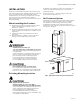
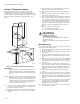
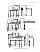
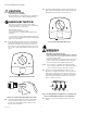
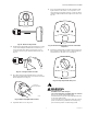
Table Of Contents

UV100E ULTRAVIOLET SYSTEMS
68-0262—09 4
Surface Treatment System
When installed next to the cooling coil, the Surface
Treatment System prevents a high percentage of the
growth of micro-organisms such as mold that may grow
on duct surfaces, coils and drain pans. Individual results
depend on careful installation and maintenance. See.
Fig. 2.
Fig. 2. Typical Surface Treatment installations.
IMPORTANT
If mounting options are limited, protect plastic or
rubber materials listed in CAUTION with ultravio-
let-resistant material such as aluminum foil duct
tape.
NOTE: When the installer is uncertain about whether the
drip pan in the installation can tolerate UV expo-
sure, consult the UV exposure white paper. This is
found by doing a search under the “technical lit-
erature” category for form no. 50-8788, at the
customer.resideo.com web site.
1. Choose a location that is readily accessible for regu-
lar inspection and cleaning. Fig. 1 and 2 and show
possible mounting locations.
2. Allow clearance in front of the device for removing
the lamp assemblies. Fig. 3 shows lamp assembly
lengths.
3. Be sure depth can accommodate full length of UV
lamp for your model as shown in Fig. 3.
4. Be sure duct mounting location is 8 in. wide mini-
mum.
5. Be sure 120 Vac electrical outlet is within range of
unit to plug in the power cord.
6. Select single-lamp and dual-lamp air treatment sys-
tem location on HVAC return air duct that is easily
accessible with a flat mounting surface. Select sur-
face treatment system location on HVAC supply air
duct that is easily accessible with a flat mounting
surface; locate the unit so the lamp can surround
the evaporator coil and drip pan with ultraviolet
light.
7. Mount to allow correct operation:
a. Do not mount upside down.
b. Do not mount with lamps facing up.
CAUTION
Sharp Edges Hazard.
Can cause personal injury.
Be careful when inserting ultraviolet device into
sheet metal cutout.
Wear protective gloves when working near sheet
metal.
Duct Mounting
Use the following instructions to mount the UV System on
the air duct of an HVAC system:
1. Disconnect power to the HVAC system before install-
ing the UV System.
2. Select the appropriate template for your model (see
Fig. 18-20).
3. Place the appropriate template for your model on
the duct surface, centering the bulb hole(s) on the
duct.
4. Mark the location on the duct for 2 in. diameter bulb
hole(s), unit mounting-screw pilot holes, and when
installing a return air model, the 1-1/2 in. airflow
sensor hole.
5. Cut 2 in. bulb hole(s) and 1-1/2 in. airflow sensor
hole in the duct. Remove any burrs. Note that the air-
flow sensor protrudes out of backside of device. Be
careful to avoid scratching or damaging the airflow
sensor.
6. Use a 3/32 in. drill for pilot holes for mounting
screws.
7. Be sure duct surface is flat after all holes are drilled.
8. Position entire base unit on duct. Be sure bulb and
airflow sensor holes in duct align with unit holes. Be
careful to avoid scratching or damaging the airflow
sensor.
9. Install unit into duct using three (or two, depending
on model) no.10, 2 in. Phillips head sheet metal
mounting screws provided. (A spare screw is pro-
vided for three-screw model.)
10. Tighten screws to 12 to 14 in.-lb so space between
case and duct is sealed.
M22859
WARNING/AVERTISSEMENT
!
Nocifs pour la pe
au nue et les
Veuillez lire et bien comprendre
l’installation
et la mainten
ance.
WARNING/
AVERTISSEMENT
!
Noc
ifs pour
la peau nu
e et les
Veuillez l
ire et bien comprendre
l’in
stal
latio
n et la ma
intenance.