
Product Overview
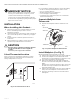
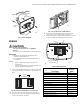
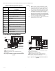
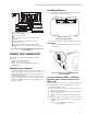
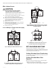
Table Of Contents
- Application
- Features
- Specifications
- Installation
- Wiring
- Power the Thermostat
- Set Calendar and Time
- Installer Setup
- Installer Setup Numbers (ISU), Settings, and Tests (Table 6)
- Main Screen
- Programming
- Operation
- Fan Sequence Operations (ISU 347, 348, 349)
- Equipment Sequence Operations (ISU 170)
- Special Programmable Mode Functions
- Special Non-Programmable Mode Functions
- Screen Locked
- Minimum-Off Timer Compressor Protection
- Temperature Sensor Operation and Checkout
- C7189U Remote Indoor Temperature Sensor
- TR21 Remote Temperature Sensor
- Troubleshooting (Table 12)

TB7100A1000 MULTIPRO™ MULTISPEED AND MULTIPURPOSE THERMOSTAT
9 63-2675—04
Fig. 22. Typical hookup of PTAC with HI and LO fan
speeds (2H/1C).
POWER THE THERMOSTAT
You can choose from three methods to power the
thermostat:
• Batteries only (AAA alkaline).
• 24 Vac direct connection only.
• 24 Vac direct connection with battery backup
(AAA alkaline).
Wiring 24 Vac Common
• Single-Transformer System—Connect the common side
of the transformer to the C screw terminal of the
thermostat wallplate. Leave the metal jumper wire in
place between Rc and R.
• Two-Transformer System—Connect the common side of
the cooling transformer to the C screw terminal of the
thermostat wallplate. Remove the metal jumper wire
between Rc and R.
Installing Batteries
1. Install two AA alkaline batteries on the back of the
thermostat as marked. See Fig. 23.
Fig. 23. Installing batteries.
2. Locate and remove tab labeled Remove. See Fig. 24.
IMPORTANT
This tab must be removed in order to set the real-
time clock.
Fig. 24. Remove tab labeled REMOVE from
thermostat back.
Locate and Mount TR21 or C7189U
Remote Indoor Temperature Sensor
(Optional)
Locate and mount the sensor in the same fashion as the
thermostat. See the Select Thermostat Location section.
Consider the following as well:
1. Be sure wire distance between sensor and thermo-
stat is less than 200 feet.
2. Mark the area on the wall selected for mounting the
sensor or junction box.
3. Sensor wire must be separate from the thermostat
cable.
4. Run wire cable to a hole at the selected wall location.
5. Pull approximately three inches of wire through the
opening.
NOTE: Color-coded, 18-gauge wire is
recommended.
COMPRESSOR CONTACTOR
M27427
CHANGEOVER VALVE
1
2
3
4
5
LOW FAN RELAY
POWER SUPPLY. PROVIDE DISCONNECT MEANS AND OVERLOAD
PROTECTION AS REQUIRED.
FACTORY INSTALLED JUMPER.
WHEN USING BATTERIES, THE 24V COMMON CONNECTION IS
OPTIONAL.
"O/B" TERMINAL SET TO CONTROL AS EITHER "O" OR "B"
IN THE INSTALLER SETUP.
OPTIONAL INDOOR REMOTE SENSOR OR REMOTE SETBACK.
WIRES MUST HAVE A CABLE SEPARATE FROM THE THERMOSTAT
CABLE.
3
L1
(HOT)
L2
1
24 VAC
AUXILIARY HEAT RELAY
4
2
INDOOR TEMPERATURE
SENSOR/REMOTE
SETBACK
5
C
G
Y
O/B
RC
R
W1
G2
G3
S1
S2
HIGH FAN RELAY
M22259A
BACK OF THERMOSTAT
BATTERY HOLDER
BATTERIES (2)
REMOVE
TAB
REMOVE DURING
INSTALLATION
M22260B
REMOVE DURING
INSTALLATION