
Product Overview
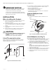
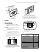
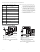
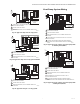
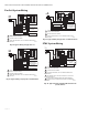
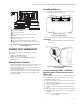
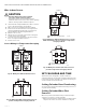
Table Of Contents
- Application
- Features
- Specifications
- Installation
- Wiring
- Power the Thermostat
- Set Calendar and Time
- Installer Setup
- Installer Setup Numbers (ISU), Settings, and Tests (Table 6)
- Main Screen
- Programming
- Operation
- Fan Sequence Operations (ISU 347, 348, 349)
- Equipment Sequence Operations (ISU 170)
- Special Programmable Mode Functions
- Special Non-Programmable Mode Functions
- Screen Locked
- Minimum-Off Timer Compressor Protection
- Temperature Sensor Operation and Checkout
- C7189U Remote Indoor Temperature Sensor
- TR21 Remote Temperature Sensor
- Troubleshooting (Table 12)

TB7100A1000 MULTIPRO™ MULTISPEED AND MULTIPURPOSE THERMOSTAT
63-2675—04 6
Table 5. Terminal Designation Descriptions. NOTES:
1. When used in a single-transformer system,
leave metal jumper wire in place between Rc
and R. If used on a two-transformer system,
remove metal jumper wire between Rc and R.
2. Common wire is optional when thermostat is
used with batteries. When using separate
transformers for heating and cooling, the com-
mon must come from the cooling transformer.
3. If thermostat is configured for a heat pump in
the Installer Setup, configure changeover valve
for cool (O-factory setting) or heat (B).
4. Sensor wires must have a cable separate from
the thermostat control cable.
Conventional System Wiring
Fig. 11. Typical wiring of single transformer 1H/1C
system.
Fig. 12. Typical hookup of dual transformer 1H/1C
system.
Terminal
Designatio
nDescription
Rc
(see Note 1)
Power for cooling—connect to secondary
side of cooling system transformer.
R
(see Note 1)
Power for heating—connect to secondary
side of heating system transformer.
Y Compressor output.
C
(see Note 2)
Common wire from secondary side of
cooling system transformer.
W1 Heat relay. Auxiliary heat relay for heat
pump, PTAC.
G Fan relay. Low fan speed for fan coil and
PTAC.
G2 Fan relay. Medium fan speed for fan coil
only.
G3 Fan relay. High fan speed for fan coil and
PTAC.
O/B
(see Note 3)
Changeover valve for heat pumps.
S1
(See Note 4)
Indoor remote sensor, remote setback, or
changeover input.
S2
(See Note 4)
Indoor remote sensor, remote setback, or
changeover input.
COMPRESSOR CONTACTOR
INDOOR TEMPERATURE
SENSOR/REMOTE
SETBACK
FAN RELAY
POWER SUPPLY. PROVIDE DISCONNECT MEANS AND OVERLOAD
PROTECTION AS REQUIRED.
FACTORY INSTALLED JUMPER.
WHEN USING BATTERIES, THE 24V COMMON CONNECTION
IS OPTIONAL.
1
2
3
C
G
Y
O/B
RC
R
W1
G2
G3
S1
S2
2
3
L1
(HOT)
L2
1
24 VAC
M27416
HEAT RELAY
COMPRESSOR CONTACTOR
M27417
HEAT RELAY
FAN RELAY
COOLING
TRANSFORMER
HEATING
TRANSFORMER
POWER SUPPLY. PROVIDE DISCONNECT MEANS AND OVERLOAD
PROTECTION AS REQUIRED.
REMOVE FACTORY INSTALLED JUMPER.
WHEN USING BATTERIES, THE 24V COMMON CONNECTION
IS OPTIONAL. WHEN USED, THE COMMON MUST CONNECT
TO THE COOLING TRANSFORMER SECONDARY.
1
3
2
3
L1
(HOT)
L2
1
24 VAC
L1
(HOT)
L2
1
24 VAC
C
G
Y
O/B
RC
R
2
INDOOR TEMPERATURE
SENSOR/REMOTE
SETBACK
W1
G2
G3
S1
S2