
Product Overview
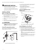
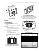
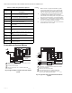
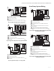
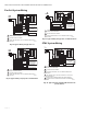
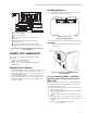
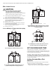
Table Of Contents
- Application
- Features
- Specifications
- Installation
- Wiring
- Power the Thermostat
- Set Calendar and Time
- Installer Setup
- Installer Setup Numbers (ISU), Settings, and Tests (Table 6)
- Main Screen
- Programming
- Operation
- Fan Sequence Operations (ISU 347, 348, 349)
- Equipment Sequence Operations (ISU 170)
- Special Programmable Mode Functions
- Special Non-Programmable Mode Functions
- Screen Locked
- Minimum-Off Timer Compressor Protection
- Temperature Sensor Operation and Checkout
- C7189U Remote Indoor Temperature Sensor
- TR21 Remote Temperature Sensor
- Troubleshooting (Table 12)

TB7100A1000 MULTIPRO™ MULTISPEED AND MULTIPURPOSE THERMOSTAT
63-2675—04 4
MERCURY NOTICE
If this control is replacing a control that contains
mercury in a sealed tube, do not place your old
control in the trash. Dispose of properly.
Contact your local waste management authority
for instructions regarding recycling and the proper
disposal of an old control.
INSTALLATION
When Installing this Product...
1. Read these instructions carefully. Failure to follow
them could damage the product or cause a
hazardous condition.
2. Check ratings given in instructions and on the prod-
uct to ensure the product is suitable for your appli-
cation.
3. Installer must be a trained, experienced service
technician.
4. After installation is complete, check out product
operation as provided in these instructions.
CAUTION
Electrical Shock or Equipment Damage Hazard.
Can shock individuals or short equipment
circuitry.
Disconnect power supply before installation.
Select Thermostat Location
Select a location for the thermostat about 5 ft (1.5m)
above the floor in an area with good air circulation at
average temperature. See Fig. 5.
Fig. 5. Select thermostat location.
Do not install the thermostat where it can be affected by:
— Drafts or dead spots behind doors and in corners.
— Hot or cold air from ducts.
— Radiant heat from sun or appliances.
— Concealed pipes and chimneys.
— Unheated (uncooled) areas such as an outside wall
behind the thermostat.
Separate Wallplate from
Thermostat
1. Separate the wallplate from the thermostat. See
Fig. 6.
Fig. 6. Separate wallplate from thermostat.
Install Wallplate (See Fig. 7)
Mount the thermostat horizontally on the wall:
1. Pull the wires through the wire hole on the wallplate.
2. Position the wallplate on the wall with the arrow
pointing up. Level the wallplate for appearance only.
3. Use a pencil to mark the mounting holes.
4. Remove the wallplate from the wall and drill two
3/16 in. holes in the wall (if drywall) as marked. For
firmer
material such as plaster, drill two 7/32 in. holes. Tap
the wall anchors (provided) into the drilled holes
until flush with the wall.
5. Pull the wires through the wire hole on the wallplate
and position the wallplate over the wall anchors.
6. Insert the mounting screws into the wall anchors
and tighten.
5 FEET
[1.5 METERS]
YES
NO
M22258
NO
NO
THERMOSTAT
WIRE HOLE
M22267
WALLPLATE