
Product Overview
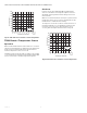
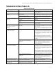
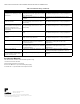
Table Of Contents
- Application
- Features
- Specifications
- Installation
- Wiring
- Power the Thermostat
- Set Calendar and Time
- Installer Setup
- Installer Setup Numbers (ISU), Settings, and Tests (Table 6)
- Main Screen
- Programming
- Operation
- Fan Sequence Operations (ISU 347, 348, 349)
- Equipment Sequence Operations (ISU 170)
- Special Programmable Mode Functions
- Special Non-Programmable Mode Functions
- Screen Locked
- Minimum-Off Timer Compressor Protection
- Temperature Sensor Operation and Checkout
- C7189U Remote Indoor Temperature Sensor
- TR21 Remote Temperature Sensor
- Troubleshooting (Table 12)
TB7100A1000 MULTIPRO™ MULTISPEED AND MULTIPURPOSE THERMOSTAT
21 63-2675—04
— HOLIDAY and OVERRIDE options are available in all
partial lockout levels.
— Pressing HOLIDAY sets the temperature to the
Unoccupied setting for the selected period of time. The
next Occupied period switches back to the program
settings.
— Pressing OVERRIDE sets the temperature to the
Occupied setting for the selected period of time. The
next Unoccupied period switches back to the program
settings.
— To cancel the temperature override and follow the
programmed schedule, press CANCEL.
PARTIAL LOCKOUT 1
This mode locks out schedule and system changes.
— User can change the temperature setpoint and fan
settings, but cannot change schedule or system
settings.
— The temporary changes last until next scheduled
period. The screen displays that time.
— To unlock the screen, see Advanced Settings section.
PARTIAL LOCKOUT 2
This mode locks out schedule, system and fan changes.
— User can change the temperature setpoint, but cannot
change schedule, system, or fan settings.
— The temporary temperature change lasts until next
scheduled period. The screen displays that time.
— To unlock the screen, see Advanced Settings section.
PARTIAL LOCKOUT 3
This mode locks out schedule, system, fan, and
temperature setpoint settings.
— Users cannot make changes to the temperature
setpoint or any schedule, system, or fan settings.
— The only features available are HOLIDAY and
OVERRIDE.
— To unlock the screen, see Advanced Settings section.
Temperature Recovery
The thermostat is equipped with a feature to eliminate
guesswork when setting a schedule. That is, the user need
not know the amount of time for the HVAC system to bring
the space to temperature (without overshoot) prior to the
scheduled time.The thermostat manages that
automatically.
Simply set the program schedule to the desired time to
have the space at comfort temperature. In addition,
program the temperature to this comfort temperature. The
thermostat activates the heating or cooling at the proper
time to reach the scheduled temperature at the scheduled
time.
NOTE: The setpoint changes gradually to use economi-
cal stages and avoid overshoot.
For example—the space will be occupied at 8:00 AM and
the desired temperature is 70°F. Set the OCC 1 period for
8:00 AM and 70°F. The thermostat turns on the heat prior
to 8:00 AM to raise the temperature to 70°F by 8:00 AM.
The thermostat provides an alert that the heating or
cooling system is coming on before a scheduled time by
displaying “Recovery” on the screen.
Minimum-Off Timer Compressor
Protection
The thermostat has an adjustable Minimum-Off Timer
that can be set from zero to five minutes (Factory Setting—
five minutes). The Minimum-Off Timer can be bypassed
through the Installer System Test or it can be bypassed
permanently by setting the Minimum-Off Timer to 0
minutes in the Installer Setup. The Minimum-Off Timer is
activated after the compressor turns off:
— If the thermostat is system powered (common wire), the
Minimum-Off Timer is also activated upon initial
startup and after power interruptions.
— If there is a call for cooling or heating during the
Minimum-Off Time, the thermostat displays “Wait.”
— When the Minimum Off Timer expires, “Cool On” or
“Heat On” (heat pumps only)” appears solidly in the
display and the compressor and fan turn on.
Temperature Sensor Operation and
Checkout
Allow outdoor or indoor temperature sensor to absorb the
air for a minimum of five minutes before taking a reading.
See the Sensor instructions for more information.
NOTE: The C7189U, TR21 and TR21-A Temperature
Sensors are calibrated at the factory and cannot
be recalibrated in the field.
C7189U Remote Indoor
Temperature Sensor
Operation
When installed with Thermostat ISU 0340 set to 3, the
remote inside temperature is displayed on the Thermostat
Home Screen as Inside Temperature. The thermostat
internal temperature sensor is not used.
The C7189U can be used to provide one remote sensor
input or as a temperature averaging network with multiple
TR21 Sensors connected, as shown in Fig. 28.
Checkout
For best results, allow C7189U Wall Mount Temperature
Sensor to absorb the air moving through the room for a
minimum of twenty minutes before taking a resistance
measurement.
With an accurate thermometer (±1°F [0.5°C]) measure the
temperature at the sensor location, allowing time for the
thermometer to stabilize before reading.
To verify sensor resistance, remove one wire from one of
C7189U wiring terminals. Use an ohmmeter to measure
the resistance across the sensor. Then compare sensor
accuracy with the temperature/resistance curve in Fig. 40.