
Product Overview
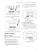
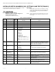
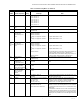
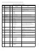
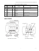
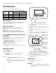
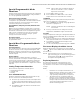
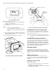
Table Of Contents
- Application
- Features
- Specifications
- Installation
- Wiring
- Power the Thermostat
- Set Calendar and Time
- Installer Setup
- Installer Setup Numbers (ISU), Settings, and Tests (Table 6)
- Main Screen
- Programming
- Operation
- Fan Sequence Operations (ISU 347, 348, 349)
- Equipment Sequence Operations (ISU 170)
- Special Programmable Mode Functions
- Special Non-Programmable Mode Functions
- Screen Locked
- Minimum-Off Timer Compressor Protection
- Temperature Sensor Operation and Checkout
- C7189U Remote Indoor Temperature Sensor
- TR21 Remote Temperature Sensor
- Troubleshooting (Table 12)

TB7100A1000 MULTIPRO™ MULTISPEED AND MULTIPURPOSE THERMOSTAT
63-2675—04 20
Fig. 37. Low battery signal.
Replace the batteries as follows:
1. Remove the thermostat from the base by pulling it
straight out. (See Fig. 38.)
2. Install two new AA alkaline batteries with proper
polarization.
NOTES:
— Always use AA alkaline batteries.
— All programming (Schedule, Date and Time)
information is retained during battery replace-
ment.
3. Place thermostat back on subbase by aligning ter-
minal screw blocks with the pins on the back of the
thermostat. (See Fig. 39.)
4. Push the thermostat straight onto the base.
Fig. 38. Removing thermostat from subbase.
Fig. 39. Placing thermostat back onto subbase.
Reading Remote Indoor Temperature
If connected to an installed remote indoor temperature
sensor, the thermostat displays the indoor temperature
from the remote sensor(s).
NOTE: If connected to an installed remote indoor tem-
perature sensor, the thermostat internal sensor is
not used.
ONE REMOTE INDOOR SENSOR INSTALLED
If one remote indoor temperature sensor is used, the
screen showing the Inside temperature reading displays
the temperature at the indoor remote sensor location.
MULTIPLE REMOTE INDOOR SENSORS INSTALLED
If more than one remote indoor sensor is used, the screen
showing the Inside temperature reading displays the
average of all the remote indoor sensors.
Screen Locked
Portions of the touch screen interface can be fully or
partially locked. See the Advanced Settings section for
information to use these features. When the thermostat
displays LOCKED, the buttons are either fully or partially
locked.
Fully Locked Screen
In this mode, the entire interface is locked and not
functional. To unlock screen, see the Advanced Settings
section. The screen continuously displays SCREEN
LOCKED.
Partially Locked Screen
When partially locked:
— Pressing a locked key prompts the screen to indicate
LOCKED for five to seven seconds.
— Pressing an unlocked key with LOCKED shown removes
LOCKED from the display.
M22383A
M22384A
WALL
WALLPLATE
M22299A
TERMINAL SCREW BLOCK
PINS ON
BACK OF
THERMOSTAT