
Install Instructions
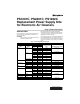
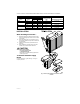
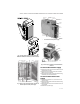
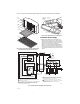
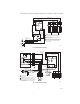
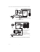
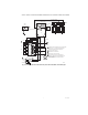
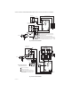
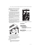

Table Of Contents

PS1201C, PS2401C, PS1202C REPLACEMENT POWER SUPPLY KITS FOR ELECTRONIC AIR CLEANERS
69-1138—03 2
a
Special international model for 50 Hz.
INSTALLATION
When Installing this Product...
1. Read these instructions carefully. Failure to follow
them could damage the product or cause a hazard-
ous condition.
2. Check the ratings given in the instructions and on
the product to make sure the product is suitable for
your application.
3. Installer must be a trained, experienced service
technician.
4. After installation is complete, check out product
operation as provided in these instructions.
CAUTION
Electric Shock Hazard.
Can cause electrical shock
or equipment damage.
Disconnect power before installing replacement
power supply board.
To Remove Old Power Supply
Board
Open access door or grille. See Figs. 1 through 7.
Open power box.
Fig. 1. Power supply location on F50A,E two-cell air
cleaners.
F58A,E 120 Vac 16 x 25 406 x 635 1.65 PS1201C02
F59A 120 Vac 16 x 12-1/2 406 x 318 0.25
220 Vac/50 Hz
a
16 x 12-1/2 406 x 318 0.25 PS2401COO
F70C 120 Vac 20 x 25 508 x 635 2.10 PS1201C02
F52F 12-1/2 x 20 317.5 x 508 1.05 PS1201C02
120 Vac/60 Hz 20 x 25 508 x 635 2.1 PS1201C02
Electronic Air Cleaner
P5 Ionizer Current
(mA) Replacement Power SupplyModel Voltage
Nominal Cell Size
in. mm