
Install Instructions
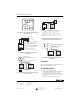
Table Of Contents

® U.S. Registered Trademark
Copyright © 2001 Honeywell • •All Rights Reserved
INSTALLATION INSTRUCTIONS
69- 1519
Motor Switch Terminal (MSTN)
APPLICATION
The MSTN is a 24 Vac, 6 VA, 50-60-cycle, two-position
motor actuator used with all AOBD, AOBD-BM, and
IOBD automatic opposed blade dampers.
The MSTN is a uni-directional motor that requires single-
pole, double-throw switching to drive the damper open
and closed. It uses a wafer switch to power the
synchronous motor for only 30 seconds while the motor
is moving between open and closed or vice-versa. When
the motor reaches the open or closed position, the
internal switches cut off the power to the motor.
The MSTN has three auxiliary end switches, rated at 1A
at 24 Vac, that can be used to control auxiliary equipment
and one additional damper, when necessary.
The MSTN can be operated by any Trol-A-Temp or
Honeywell zoning panel. It also can be operated by any
spdt switch or relay contact. It can be controlled with five
or three wires, depending on the application.
INSTALLATION
When Installing this Product...
1.
Read these instructions carefully. Failure to follow
them could damage the product or cause a hazard-
ous condition.
2.
Check the ratings given in the instructions and on
the product to make sure the product is suitable for
your application.
3.
Installer must be a trained, experienced service
technician.
4.
After installation is complete, check out product
operation as provided in these instructions.
Planning the Installation
Before installing the motor:
• Check the position of the MSTN.
• Use an ohmmeter and check for continuity between
terminals 2 and 4, and 2 and 6, with no power to the
motor.
a
When the motor is between the open and closed posi-
tion, place 24 Vac across terminals 1 and 4. Jumper ter-
minals 2 and 5; the motor rotates to the open position
and stops. Install the motor on the damper and set the
damper linkage to open. The crank arm points in toward
the damper when open.
Installing the MSTN
To install the MSTN into the plastic motor box attached to
the motor:
NOTE: When used as replacement motor, remember
that the MSTN is shipped in the open position.
To confirm this for continuity across terminals 2
and 4, there should be none. See Fig.1
1.
Insert the motor shaft into the motor box and
through the hole in the box.
2.
Insert two small screws through the motor box to
hold the motor in place.
3.
Place the motor crank arm on the motor shaft and
tighten the set screws.
WIRING
See Fig. 2-5 for wiring diagrams.
Continuity
Between
Terminals 2 and 4
Continuity
Between
Terminals 2 and 6
Motor
Position
Yes No Closed
No Yes Open
Yes Yes Between
positions
a